In this tutorial you’ll create a zombie horde shooter game with Unreal Engine 5 using blueprints.
The game is simple but is packed with tons of behind the scenes features that will allow you to understand the “why” behind the “how” a game is created in Unreal Engine 5.
Here’s a short preview of the game that we’ll create:
Download The Assets And Complete Project For This Tutorial
You can download the assets and the complete project for this tutorial by clicking on the button above.
In the downloaded files you’ll find assets to follow with this tutorial and the complete project you can use as a reference to inspect the code.
Important Information Before We Start
This tutorial is for beginners as well as intermediate developers. However, it’s not meant for complete beginners who never created even a simple game in Unreal Engine.
We expect you to know your way around Unreal Engine and its interface. We also expect that you know the basics and a little above basics of working with blueprints.
If you’re a complete beginner, we recommend that you first go through our Parasite Platformer tutorial which will allow you to understand all the basics of creating a game in Unreal Engine. The link to the tutorial is below:
Creating The Project
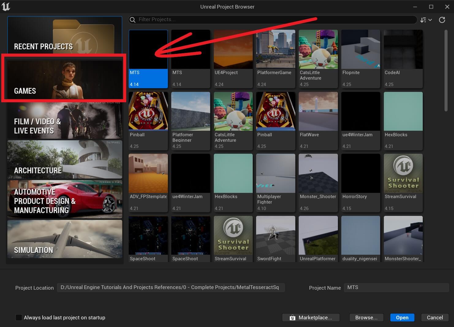
Open your Unreal Engine 5 editor and select games on the left side:
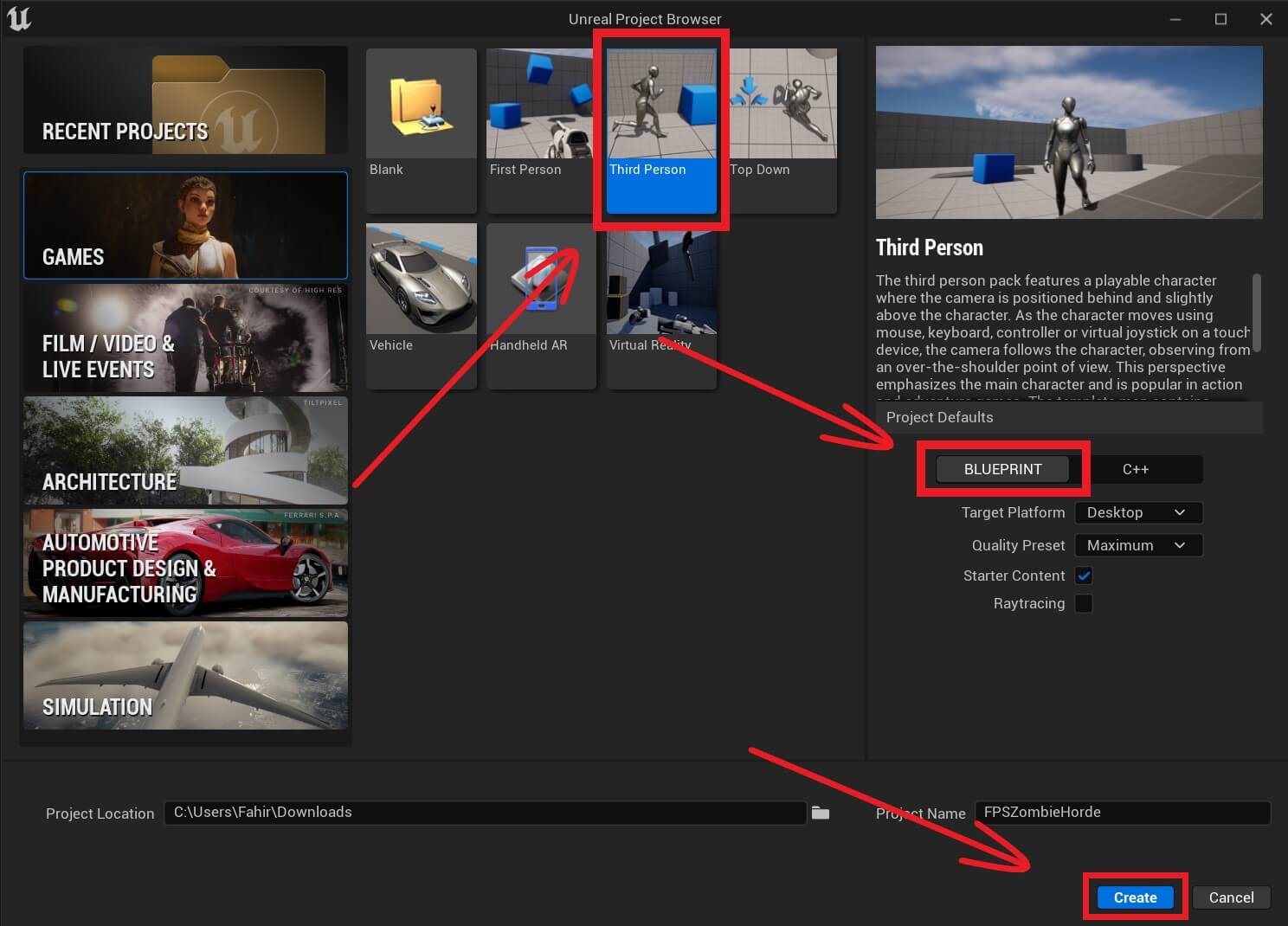
In the next window select ThirdPerson project, Blueprints, give the project a name and press the Create button:
Importing Assets
Unzip and open the assets folder that you downloaded by pressing the green button above.
Inside you’ll find 3 folders:
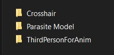
Open the folder with the name ThirdPersonForAnim. The ThirdPersonForAnim is actually an Unreal Engine project, and you’ll need Unreal Engine version 4.22 to open it.
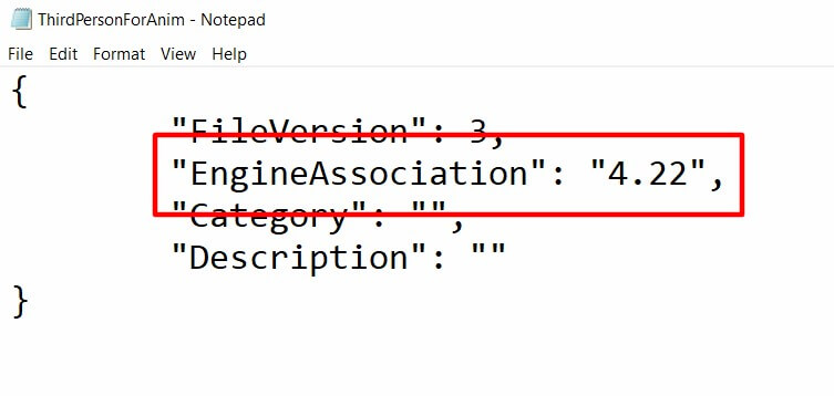
In case you don’t know how to check with which engine version the project is created, simply Right Click on the .uproject icon, then under Open With select Notepad:
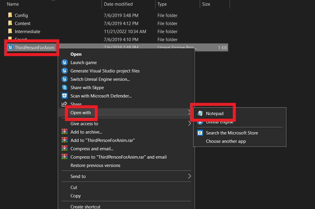
The EngineAssociation inside the notepad will indicate the Unreal Engine version with which the particular project is created:
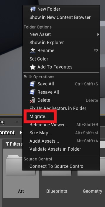
When you open the project, select the Art folder then Right Click on it and select Migrate:
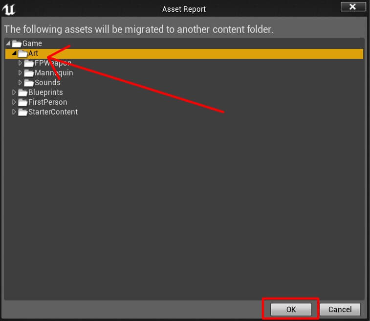
A new window called Asset Report will open. Inside that window select the Art folder again, and press Ok:
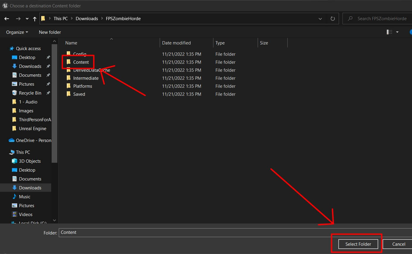
A new window will open prompting you to choose a destination where the select folder, in this case Art folder, will be migrated.
Since we’re going to use the assets in the Art folder inside our new FPS Zombie Horde project, locate the folder where you stored your FPS Zombie Horde project.
Mine is located in the Downloads folder:
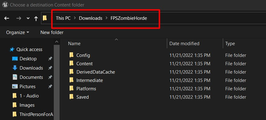
From there, select the Content folder and the press the Select Folder button:
In the new window that appears press the Yes To All button:

This will copy all the files from the Art folder in the ThirdPersonForAnim project, and paste them inside our FPS Zombie Horde project in Unreal Engine 5:
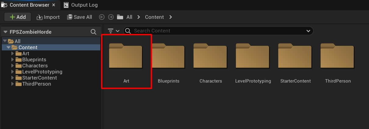
You can always use this method to transfer files from one Unreal Engine project to another.
Creating Our Custom Player Character
Inside the Content browser I’ve created a new folder and named it FPS_ZombieHorde:
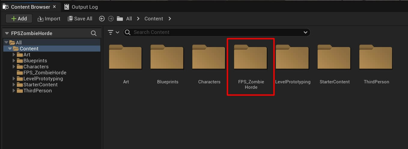
Inside this folder we’ll store everything we create for our game project. We’ll start with the Player_Character folder:
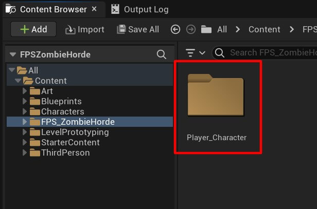
Inside the Player_Character folder Right Click and create a new blueprint:
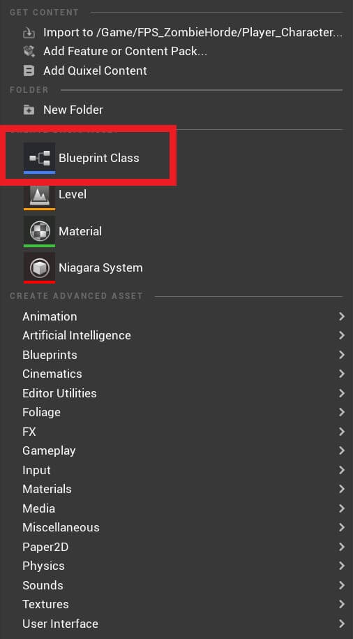
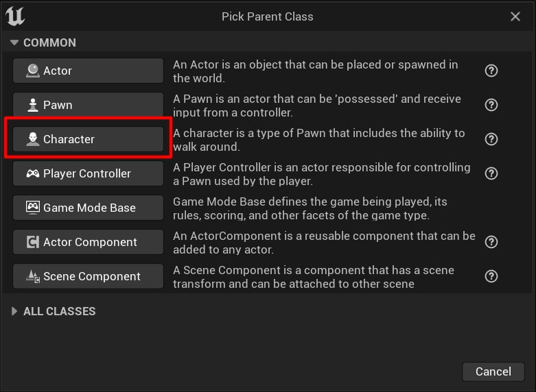
The parent class is going to be Character:
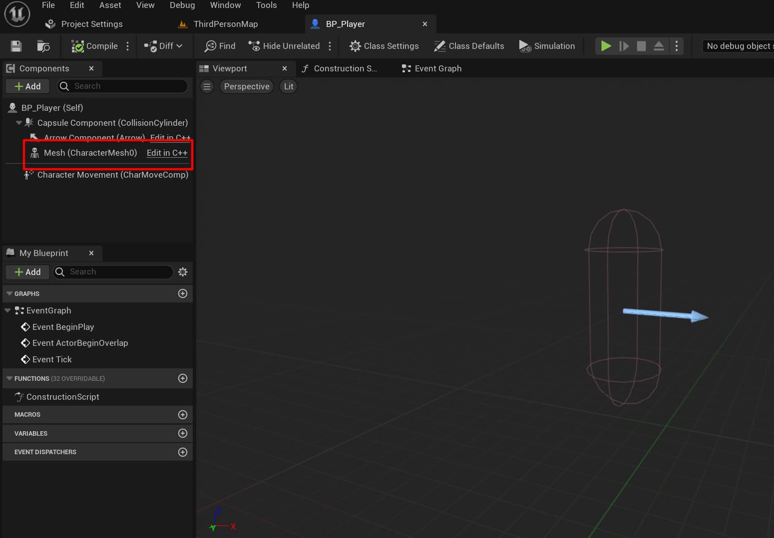
Name the blueprint BP_Player and open it in the editor window. Inside the BP_Player editor, click on the mesh component in the Component tab at the top right corner:
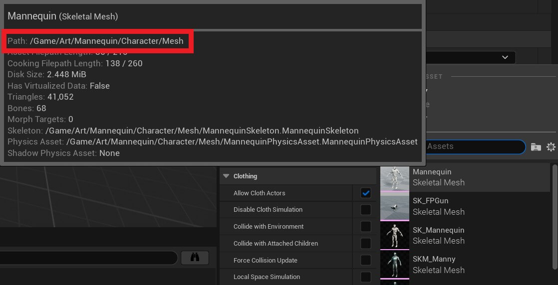
Now inside the Details tab on the right side, under the Mesh option for the Skeletal Mesh 3D object we are going to select the Mannequin 3D object:
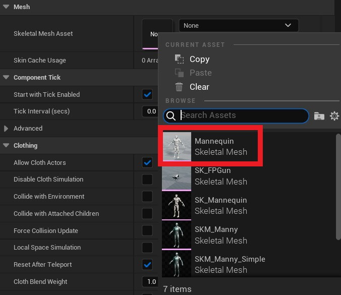
But make sure that you select the one which is located in the Art folder. And you can know that by hover over the Mannequin 3D object and check the path where the model is stored:
When you select the Mannequin model, set the following values in his transform options:

The location Z and rotation Z values we change are just going to move the character down and rotate him so that he faces the forward direction within his Capsule component:
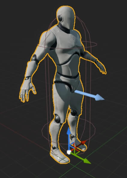
We’re also going to resize his Capsule component by setting the radius to 17:

Next, inside the Component tab click on the Add button and filter for Spring Arm:
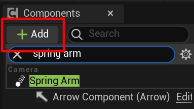
Rename the Spring Arm component to Camera Arm and it’s Z location to 48:

This is going to move the Spring Arm component up. Now select the Camera Arm component, click on the Add button and attach a Camera component:
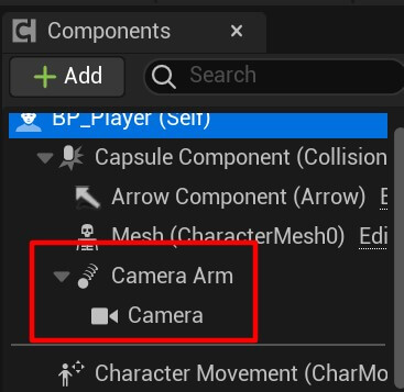
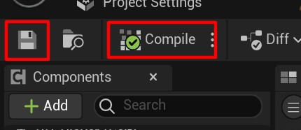
Save and compile the changes by pressing the Save then Compile button at the top left corner:
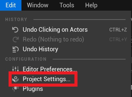
Now we’re going to go under Edit -> Project Settings:
Under Project -> Maps & Modes we are going to change the Default Pawn class to our BP_Player:

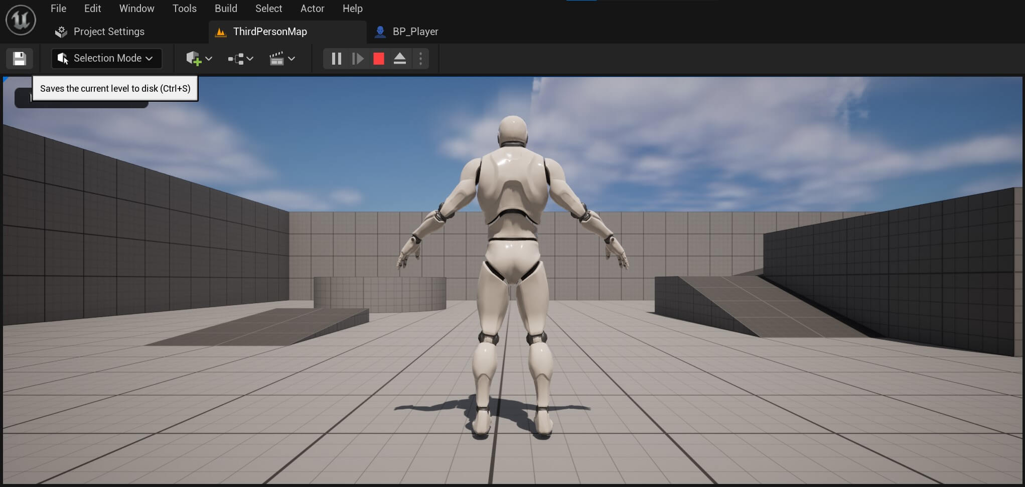
When we press the Play button we now see our player in the gameplay world:
Introduction To Enhanced Input - New Unreal Engine Input System
To move our character we are going to use the new Enhanced Input that Unreal introduced.
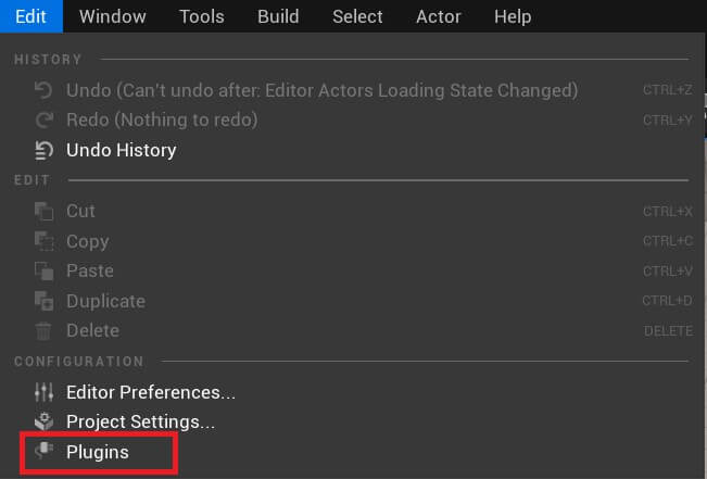
If you followed all the steps to create the project as we did, you should already have ehanced input in your project, and you can easily check that by going under Edit -> Plugins:
In the search type “enhanced input:”
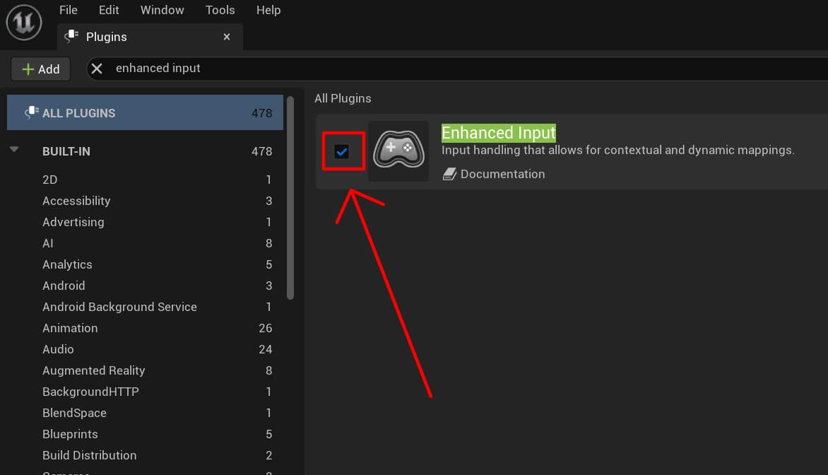
If the checkbox is checked like in the image above then you’re good to go, if not, enable the enhanced input plugin by checking the checkbox and then you’ll be promted to restart Unreal Engine for the changes to take effect.
Also make sure that under Project Settings -> Input -> Default Classes the Default Player Input class is set to EnhancedPlayerInput and the DefaultInputComponentClass is set to EnhancedInputComponent:
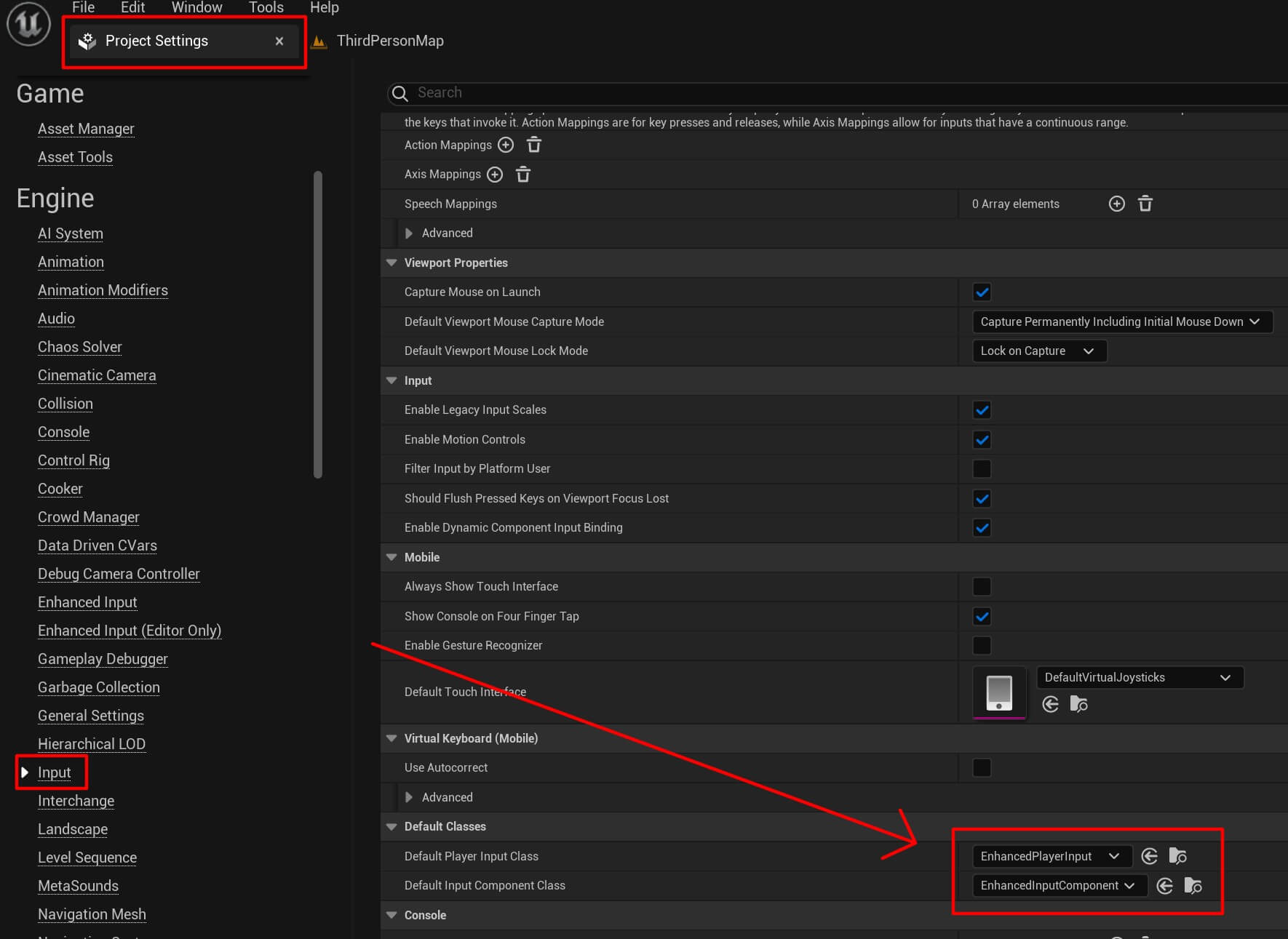
Essentially what’s the deal with the new EnhancedInput is that Unreal Engine gave us full control over the input system. The options we have now were part of the engine for a long time but they were not easily accessible as they are now.
That being said, since we’re given full control of the input system we are the ones who need to define that system and how we want to use it.
So, if we want to move the game character left and right, we need to define an Input Action and give it values so that we can use them in the blueprint to move the player. And the same goes for the rotation of the player using the mouse.
We’re going to start by defining the Input Action for the movement. Inside the FPS_ZombieHorde folder Right Click and create a new folder and name it Input.
Inside the Input folder Right Click -> Input Action:
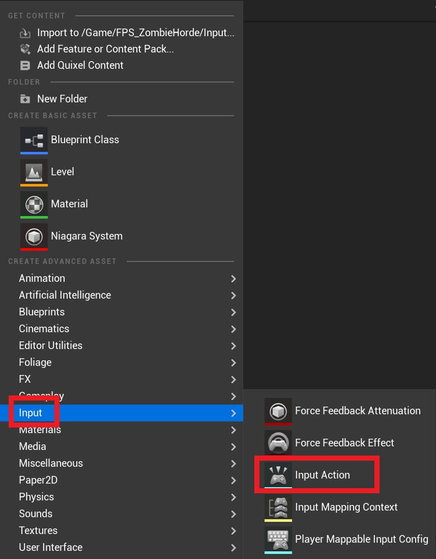
Rename the input action to IA_MoveForward:
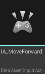
Double click the IA_MoveForward and these are the options you’ll see when you open it in the editor:
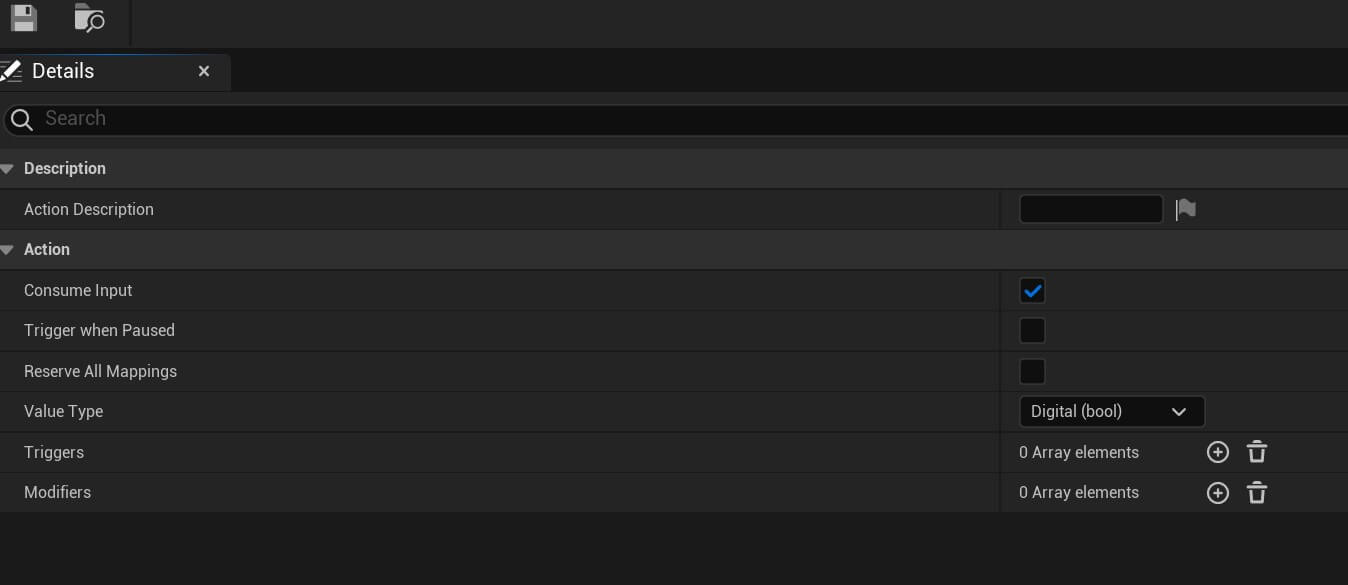
The Action Description option allows us to give a description to the input action we created, for this one we can write MoveForward.
Under the Action tab we have 6 options and this is what they mean:
- Consume Input – can the action take input e.g. can we bind a button to it, press that button and trigger this action
- Trigger when Pause – can this action be trigger if the game is paused
- Reserve All Mappings – the action mappings of this action, which are used to store input actions so we can use them in our game, can’t be overriden by higher priority context mappings
- Value Type – the value this input action will return
- Triggers – triggers that you must trigger in order to invoke the particular input action
- Modifiers – modifiers that are applied to the final action value e.g. value type
Click on the drop-down list for the Type Value and select the Axis1D(float) option:

This is the equivalent of using the Scale option in the old Input system:

By selecting the Axis1D(float) option we’ve enabled this input action to return a float value which we’ll use to move the player character.
Now following the same instructions above, create 4 more input actions and name them: IA_LookUp, IA_LookRight, IA_MoveRight, IA_My_Jump:
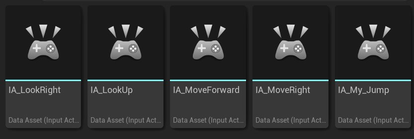
Set the following options for the input actions.
IA_MoveRight:
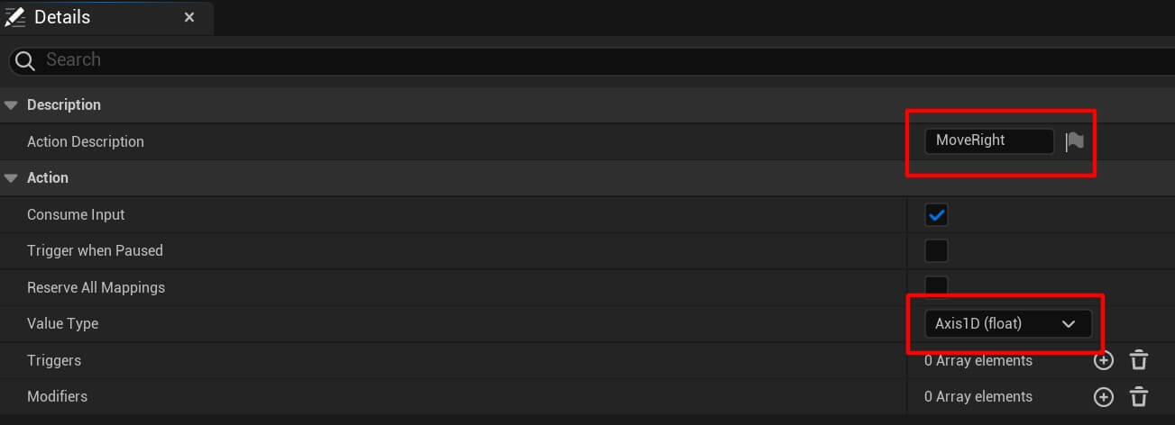
IA_My_Jump, btw, I named this input action my jump because there is a default IA_Jump and I don’t want them to intersect with each other:
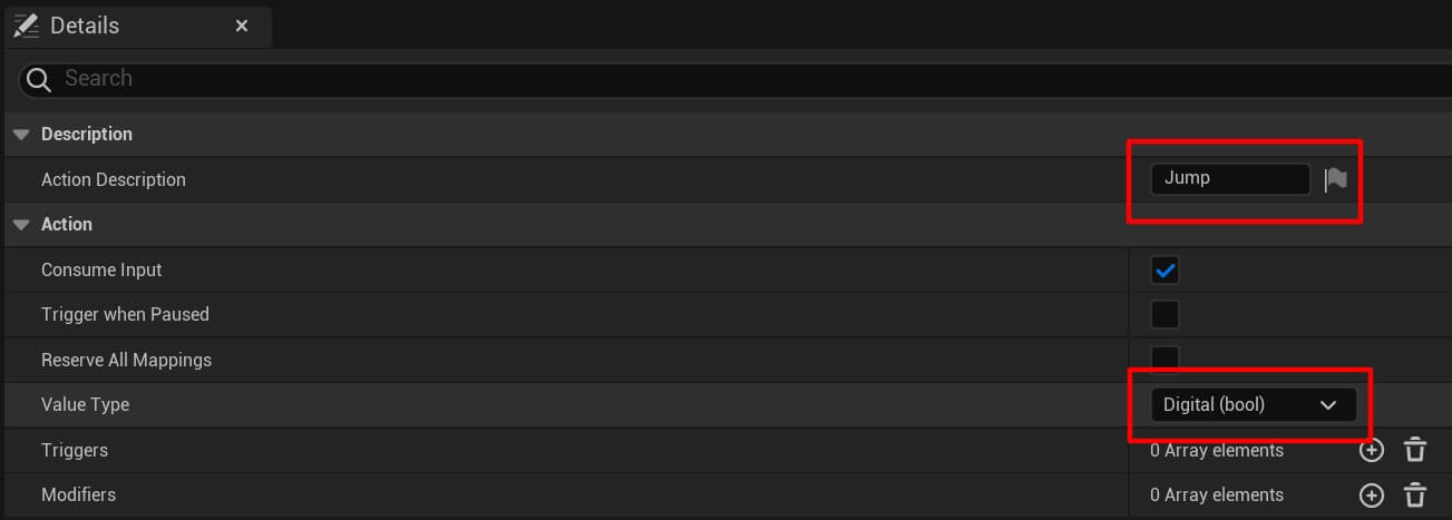
IA_LookRight:

IA_LookUp:
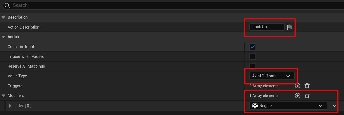
As you noticed in the IA_LookUp for the modifiers option we set the Negate.
The way it works is you press the + button for the array elements, and from the drop-down list search for Negate:

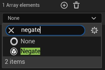
Using the Negate option is equivalent to setting the Scale to negative value for the old input system:

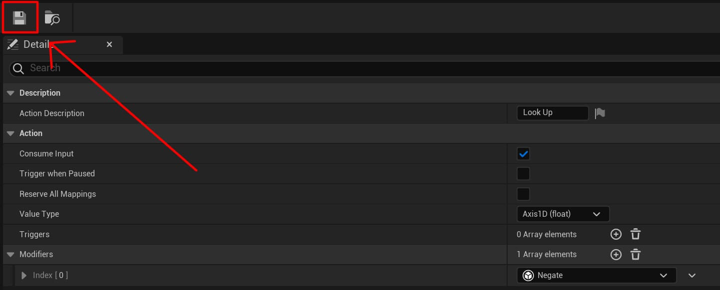
When you finish modifying the settings for every input action, press the Save button at top left corner for every individual input action:
Binding The Input Actions With Input Mapping Context
In the old input system to bind the actions or axis to keys, we would simply select the appropriate key from the drop down list:

In the example above, we’ll trigger the MoveForward axis when we press the W key on the keyboard.
Now to bind the input actions we created with keys we can press to trigger them we need to use Input Mapping Context.
Inside the Input folder, Right Click -> Input -> Input Mapping Context:
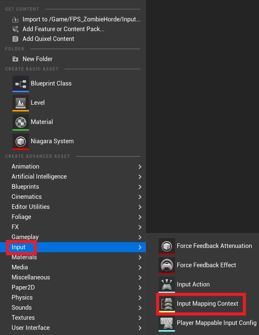
Give it a name IMC_MovementAndLook and open it in the editor.
In the mappings tab for the mappings click the + button 5 times and in the search bar for every one of the mappings you added search the appropriate mappings we created:

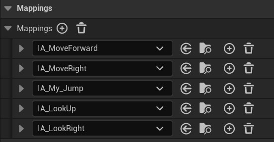
For the IA_MoveForward set the W and the S key, and for the S key add a negative modifier:
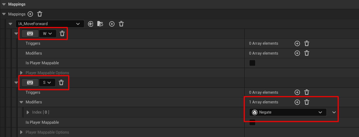
You select the keyboard keys the same way you would select them in the old input system. And the negative modifier can be added the same way we showed in the previous example above.
Now modify the IA_MoveRight:
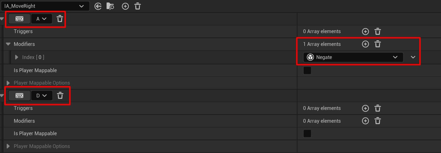
The negative modifier is set for the A key because when we press the A key we go in the negative side.
Next modify IA_My_Jump:
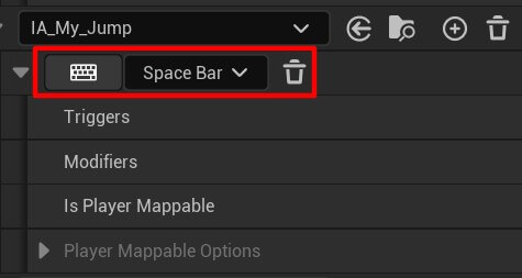
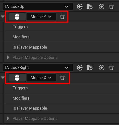
And lastly we have IA_LookUp and IA_LookRight:
Moving The Player Character With The Enhanced Input System
To move the player character the first thing we need to do is get a reference to the Enhanced Input Local Player Subsystem.
And we get that reference from the player controller:
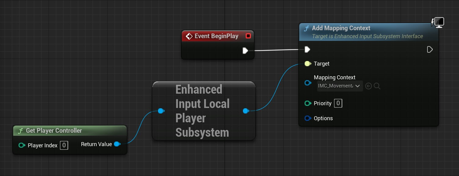
You can copy the nodes from here:
The tool from where you can copy the nodes is called blueprintUE and if you don’t know how it works you can check it out by clickin the link below:
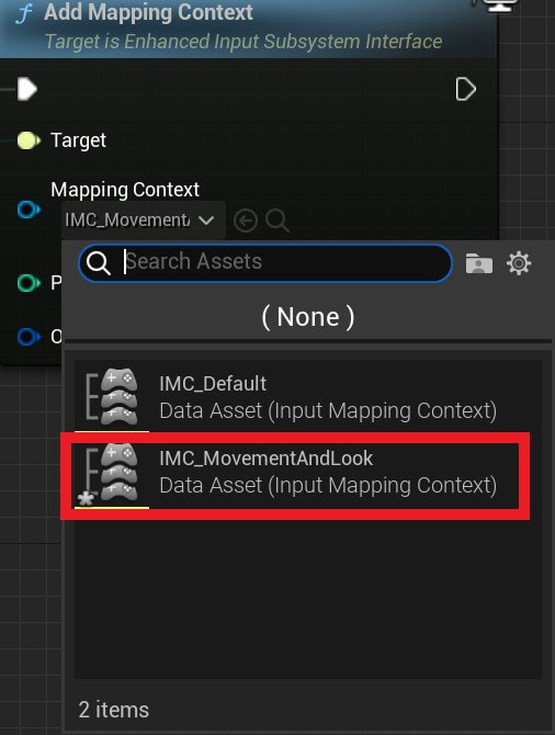
One thing to note is in the Add Mapping Context node for the Mapping Context option you need to select the IMC_MovementAndLook mapping context we created:
To move the player character we’ll add the following nodes:
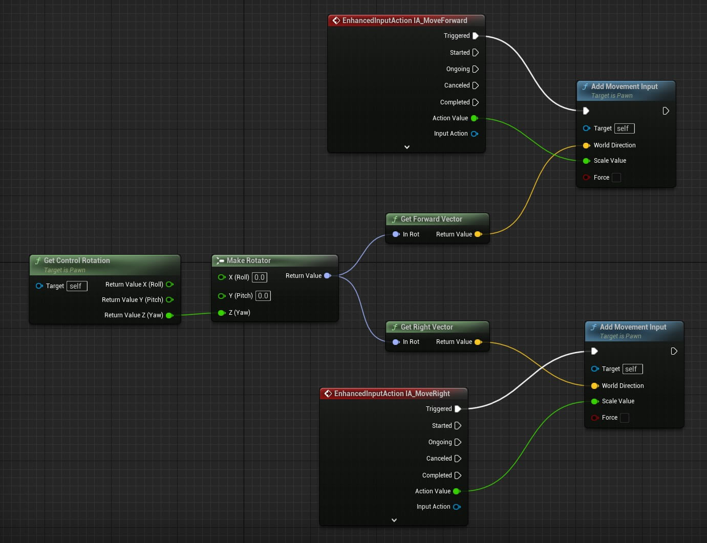
You can copy the nodes from here:
This is a common code used to move a character actor in Unreal Engine that we used in the previous tutorials.
From the control rotation we get the forward and right vector that we pass to the Add Movement Input node which makes sure that the character goes in the appropriate rotation direction.
The only difference between this code and the one we’ve been using in previous tutorials is that we are using the ehnaced input action nodes.
Specifically we’re using the IA_MoveForward and IA_MoveRight input actions that we created in the previous steps.
Next, we need to rotate the character with mouse controls, and for that we’re going to add the following nodes:
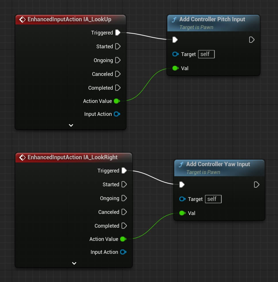
You can copy the nodes from here:
Again we’re using the ehnaced input system, specifically IA_LookUp and IA_LookRight.
The last we need to do to make sure our character is rotating the right way is we need to select the Camera Arm component and in the Details tab for the Camera Settings options check the checkbox for Use Pawn Control Rotation:
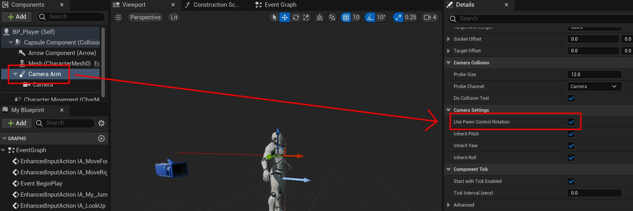
This is going to make sure the character’s camera rotates up and down when we move the mouse up and down.
Also, make sure that the Pawn settings for the BP_Player (self) are set as the following:
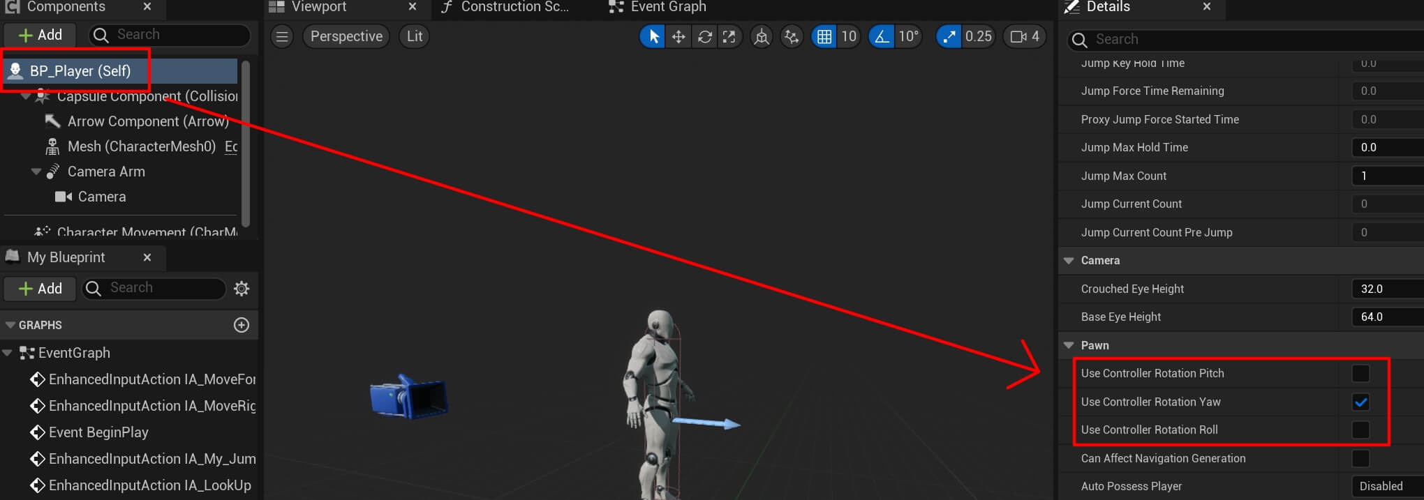
Only the Use Controller Rotation Yaw checkbox should be checked and this is going to make sure that when we move the mouse left and right the character will rotate left and right.
Now we can test the game by pressing the play button and this is how it looks like:
Character Jump And Sprint
Before make our character jump and sprint, we’re going to create variables that are going to enable us to do that and also variables for controlling the overall behavior of the player character.
Inside the Event Graph of the BP_Player blueprint create the following variables:
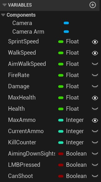
Set the SprintSpeed, WalkSpeed, MaxHealth, and MaxAmmo variables to be public.
Set the default values for the variables as follows:


The variable names are selfexplanatory for what we are going to use them.
But we’ll cover every variable when we use it so that we don’t go over the purpose of every variable now.
Moving forward, first we are going to make the character jump with the following code:

You can copy the nodes from here:
First you’ll notice that we’re using IA_My_Jump as a trigger to make the character jump.
Second, we’re using the AimingDownSights variable as a condition to determine if we can jump or not.
This varilable will be true when we aim with the gun, in that case we are not going to be able to jump with the character. When we’re not aiming that’s when we are able to jump.
This is how it looks like in the game:
Before we make the character sprint, we need to create an input action for that.
We always say the best way to learn is by practice, so your assignment is to create the input action for spriting that is going to be triggered by pressing the Left Shift key.
Of course, we’re going to give you a solution here, but we highly encourage you to try and create it on your own first, even if you fail it doesn’t matter, the important thing is that you try.
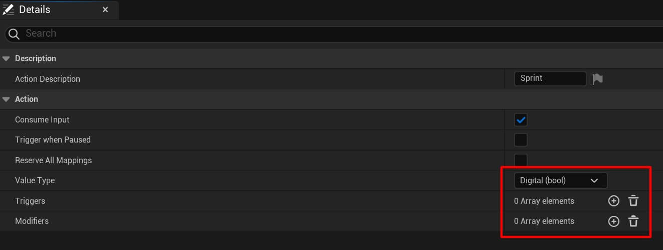
So again, inside the Input folder we’re going to Right Click -> Input -> Input Action, give it a name IA_Sprint and set the following configuration:
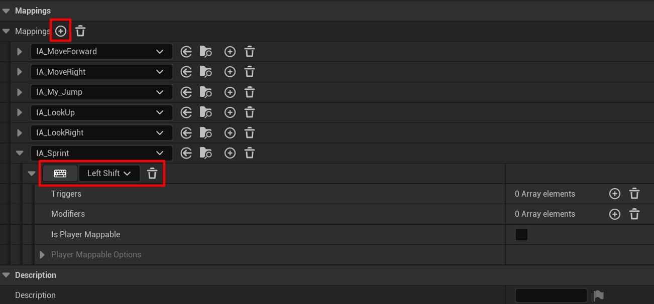
Inside the IMC_MovementAndLook we’re going to create a new mapping for the sprint input action and make it trigger when we press the Left Shift key:
To make our character spring we are going to add the following code:

You can copy the nodes from here:
Again we’re using AimingDownSights variable to test if we are aiming. If we are not aiming then we can sprint.
And we do that with the help of the character movement component which is by default attached on every blueprint that inherits from the Character:
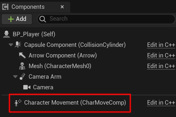
When we are sprinting, we simply change the Max Walk Speed variable from the character movement to the value of our custom Sprint Speed variable.
Next we set the Orient Rotation To Movement to true. And this variable is going to make our player character rotate in the movement direction, meaning if we press the W key to move him forward, he’ll rotate to face the forward direction.
If we press the D key to move the character right, he’ll rotate to face the right direction. And we’ll see this in a moment when we test this feature.
While we’re sprinting we disable the use of the controller’s yaw rotation by setting the Use Controller Yaw Rotation variable to false because we are rotating the character with the Orient Rotation To Movement.
When we release the Left Shift button we do the opposite. We set the Max Walk Speed to the value of our Walk Speed variable, we disable the Orient Rotation To Movement, and we enable the Use Controller Yaw Rotation.
This is how it looks like in the game:
Whenever we pressed the Left Shift key the character was rotation in the movement direction and he moved with higher speed.
When we released the Left Shift key the character returned to his walk speed.
Before we move on to the next feature, we are going to create a custom event to stop the character from sprinting when we start to aim.
So again, inside the BP_Player blueprint editor, Right Click and search for custom event:
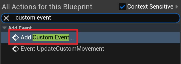
Give the custom event name Unsprint Event and plug it in the following node:
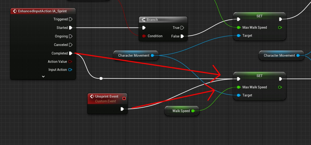
Basically the Unsprint custom event is going stop the character from sprinting if we start aiming while the character was sprinting and when that happens the Max Walk Speed is set to the value of our custom Walk Speed, Orient Rotation To Movement is set to false, and Use Controller Yaw Rotation to true – same thing that happens when we release the Left Shift key and the player stops sprinting.
Character Animation Blueprint
To animate the character we need to create the animation blueprint. Inside the FPS_ZombieHorde -> Player_Character folder Right Click -> Animation -> Animation Blueprint:
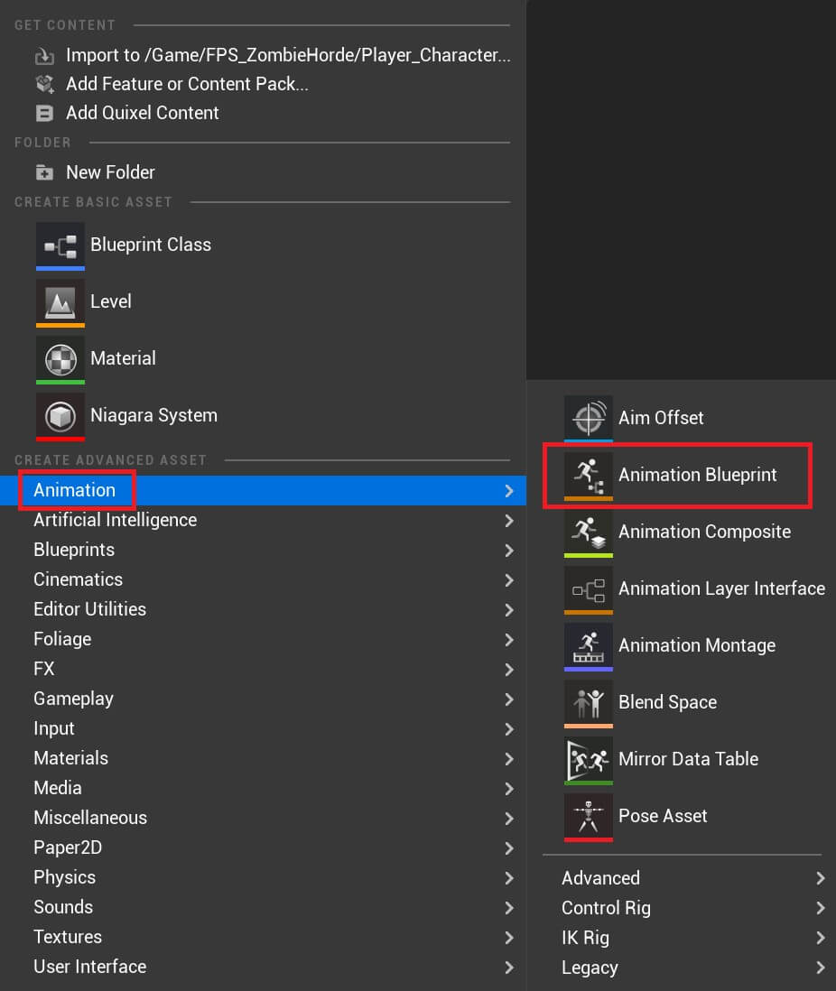
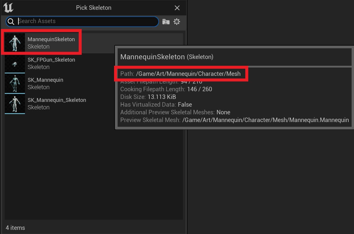
In the Create Animation Blueprint window select the MannequinSkeleton the one which is located in the Art folder:
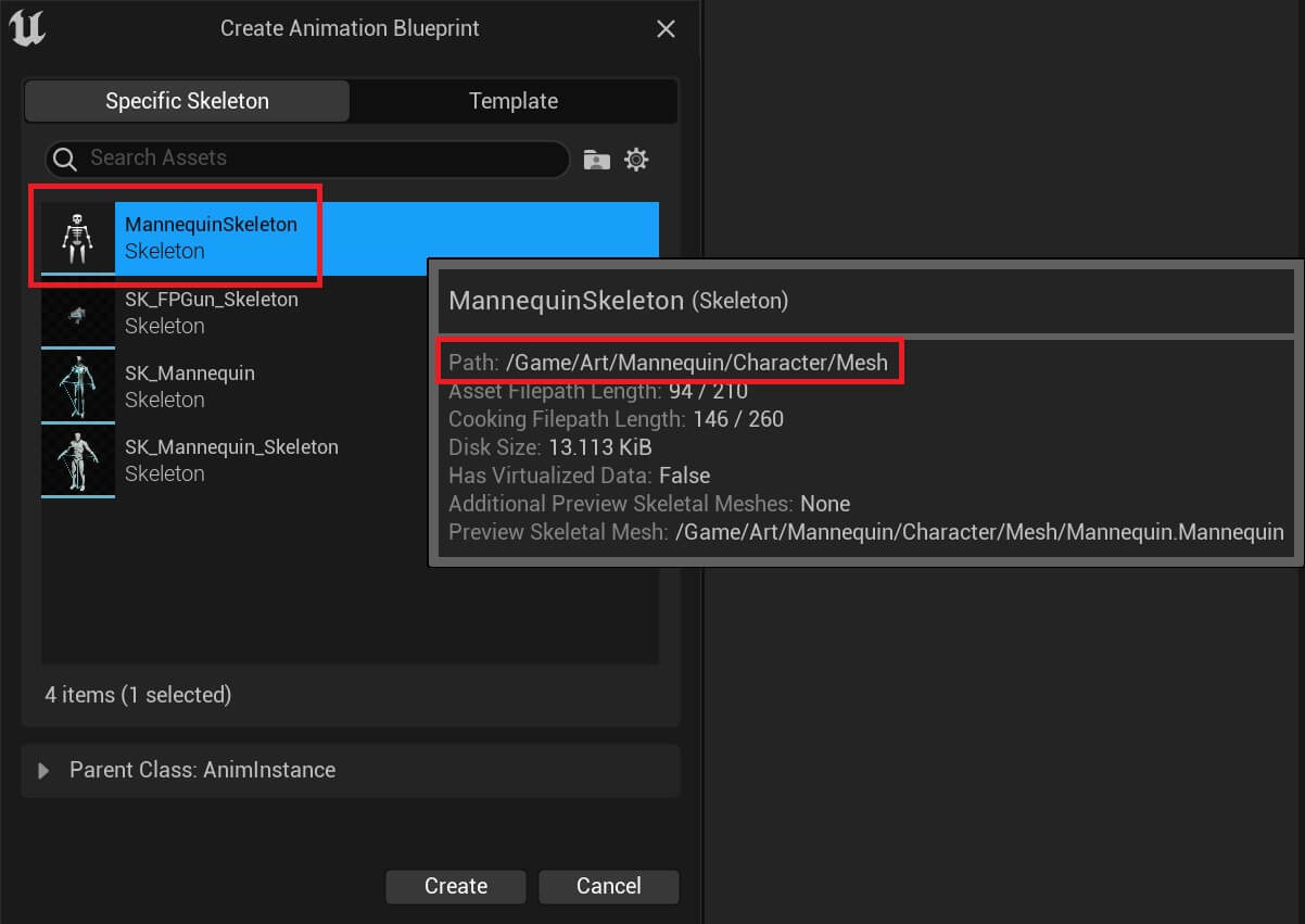
We need to select the skeleton from the Art folder otherwise the animations wont work.
Give the new animation blueprint name BP_Player_Animation and open it in the editor. Next, inside the BP_Player_Animation AnimGraph we are going to create a new state machine by Right Click -> State Machine:
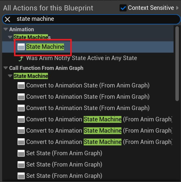
Give that state machine name Default:
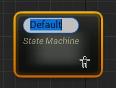
And then double click it and opet it’s graph editor. Inside the Default state machine editor Right Click -> State:
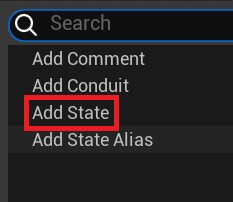
And create the following states:
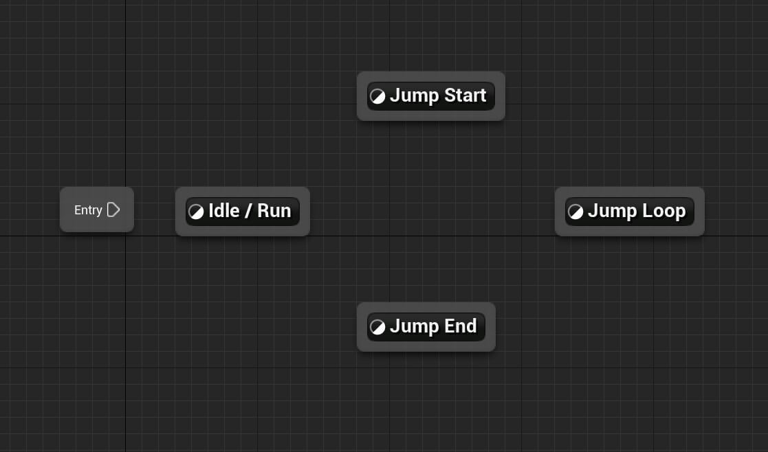
The first animation that’s going to be played is the Idle / Run and you set that by dragging the arrow from the Entry node on the Idle / Run node:

Now open the Idle / Run node animation because that’s the first animation we’re going to create.
Inside the Graph editor for the Idle / Run create the following variables:
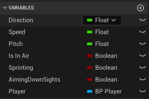
In case you don’t know where the variable tab is located, here it is:
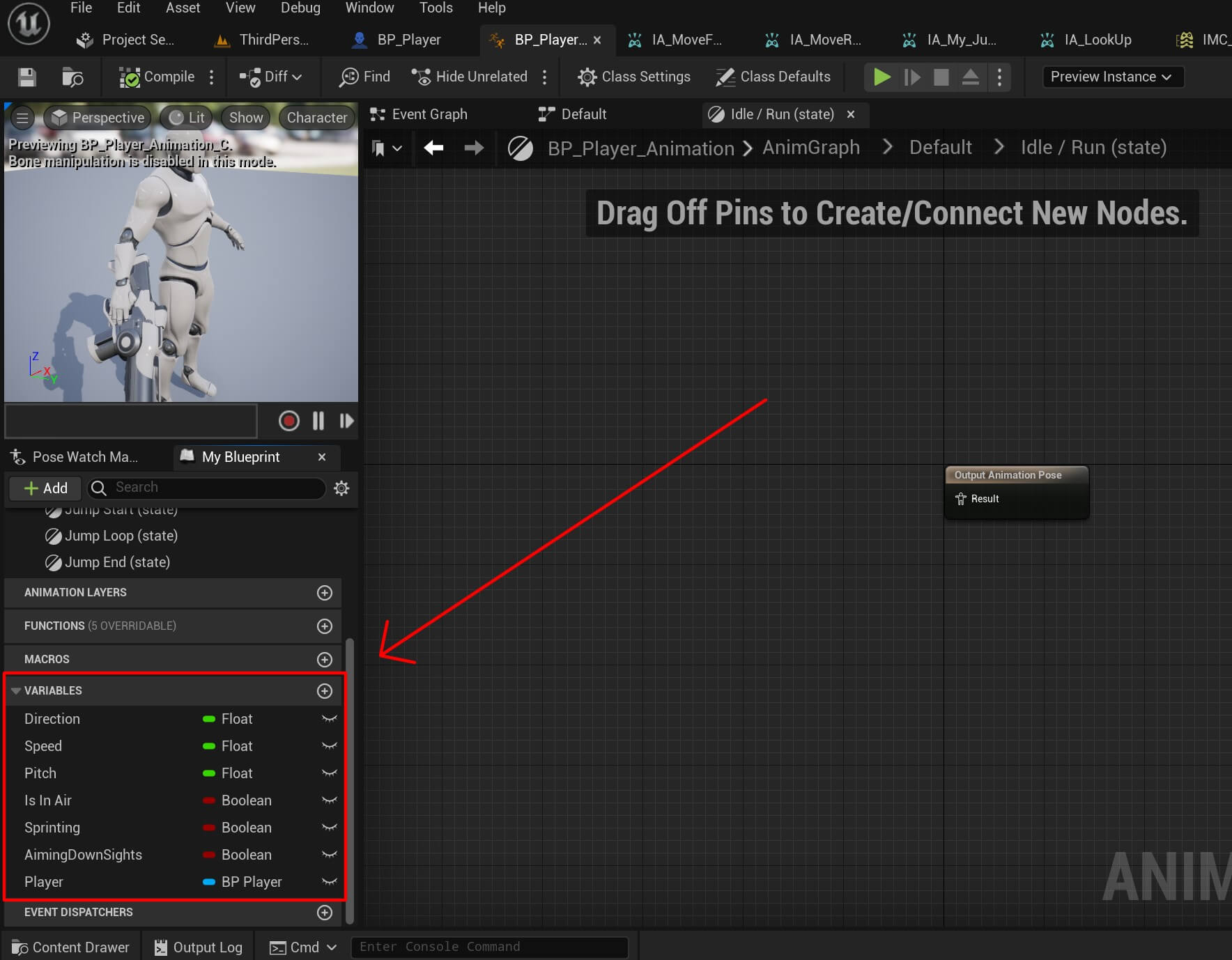
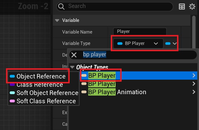
For the last variable called Player, this is going to be a reference to our BP_Player blueprint, and in order to get that reference click on the drop-down list for the Player variable and search for BP_Player and select Object Reference:
Movement Blend Space
Next we are going to create a blend space which we’ll use to blend animations into each other for smoother transitions and natural look.
Inside the Player_Character folder Right Click and create a new folder called Blend_Spaces.
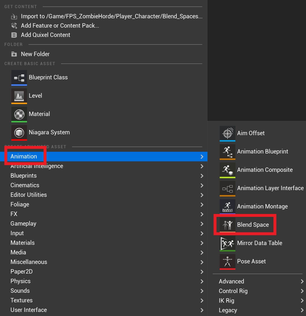
Inside of that folder Right Click -> Animation -> Blend Space:
Again we need to select the Skeleton for the animation and again make sure that you select the Skeleton which is inside the Art folder:
Give the blendspace a name BS_Movement which stands for blend space movement not bs, and double click the blend space to open it in the editor.
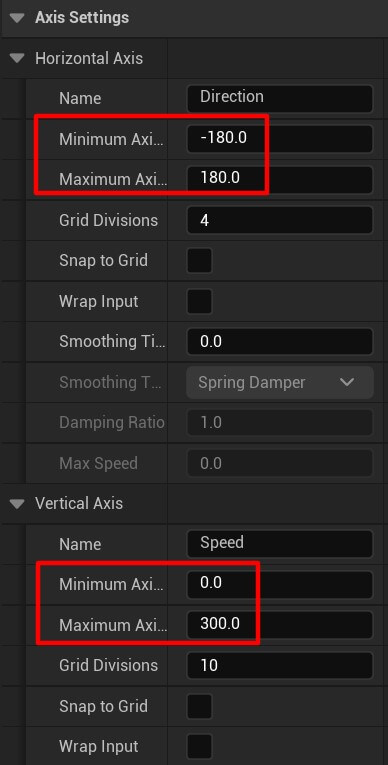
Inside the blend space editor on the left side you’ll see a tab called Axis Settings, set the following values for the Horizontal and Vertical axis:
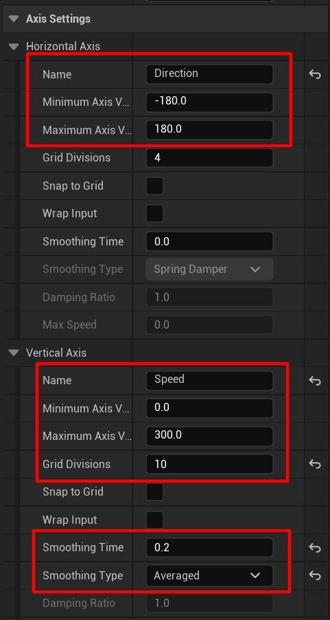
The minimum and maximum axis value range we set for both Horizontal and Vertical axis are going to be used to play animations for the appropriate values.
For example, let’s say the value of Horizontal axis is 57 and the value for Vertical is 80 the animations we set on the grid, which we’ll do in a moment, are going to blend into each other based on those numbers, and we’ll see how that looks like.
The Grid Divisions we set for the Vertical axis referer to the grids where we are going to put the animations we want to play:
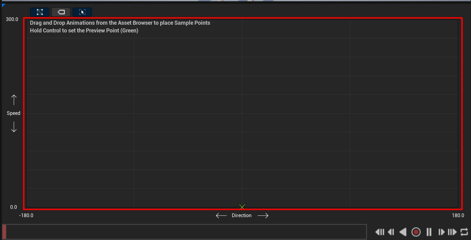
And lastly the Smoothing Time we set to 0.2 and Smoothing Type we set to Averaged is used to move smoothly accorss the blend space e.g. the transition between the animations is going to be smooth.
Now we can start adding the animations which are located in the Art folder, but we can use the Asset Browser tab in the bottom right corner and in the search bar filter for animations.
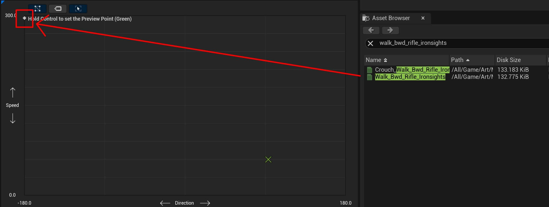
The first animation is going to be walk_bwd_rifle_ironsights, so type that in the search and put that animation in the top left corner of the animation grid system:
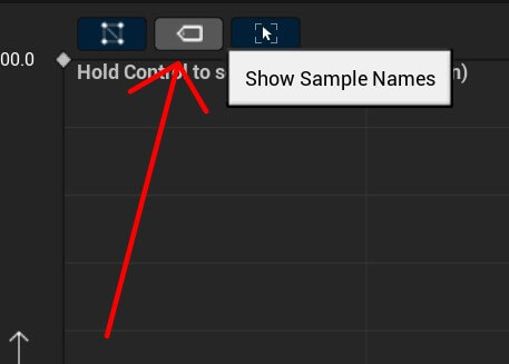
You can click on the Show Sample Names button and it will preview the names of the animations in the grid:
Next, type walk_lt_rifle_ironsights in the Asset Browser and drag the animation to the right of the previous one:
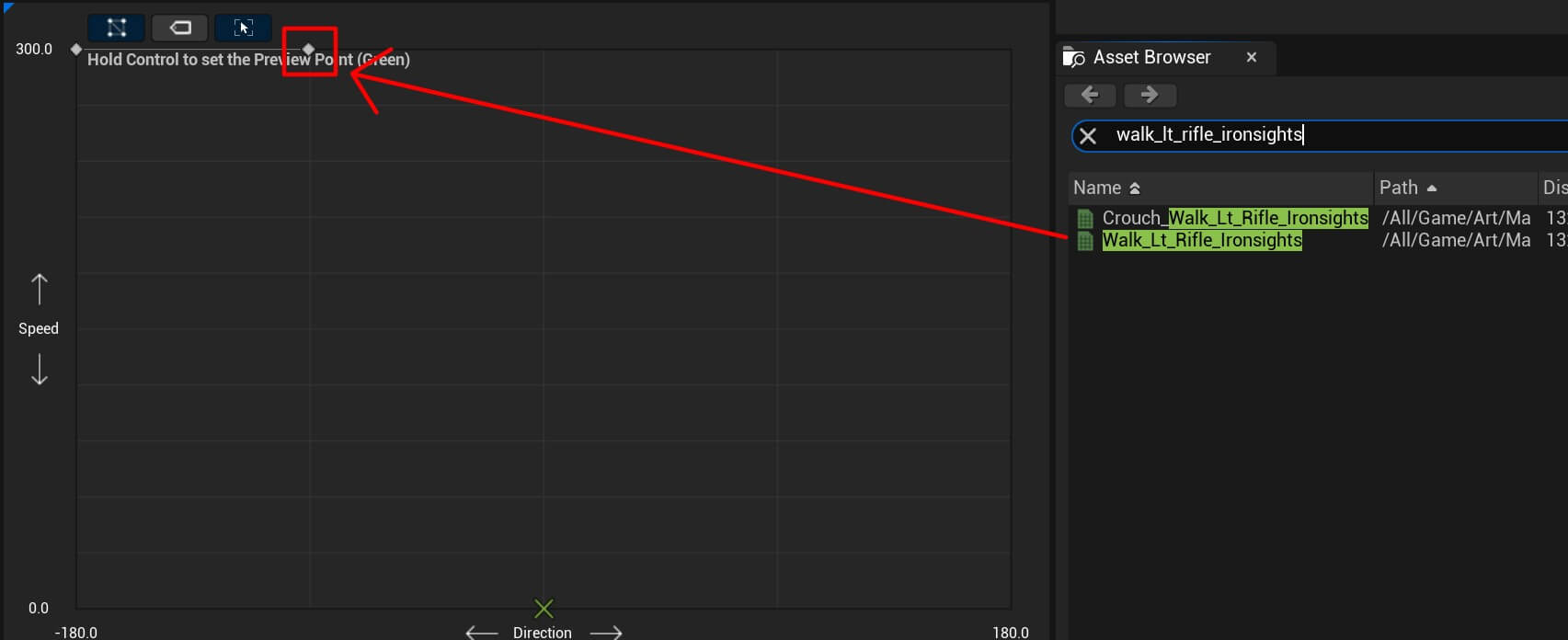
For the remaining animations I’m just going to put the name of the animation you should type in the Asset Browser and show you were to put the animation on the grid.
Starting with walk_fwd_rifle_ironsights:
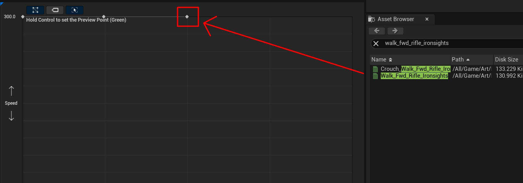
Next animation is walk_rt_rifle_ironsights:

Now we have the walk_bwd_rifle_ironsights animation:

The last animation is idle_rifle_ironsights and we’re going to place it at the bottom part of the grid on all 5 places:
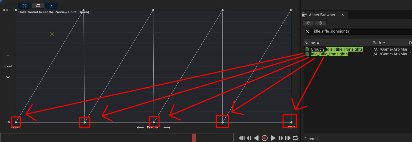
One thing you’ll notice in the animation tab where we placed all the animations is that it has 2 axis. One called Speed and the other called Direction which are the same axis we modified in the Axis Settings:
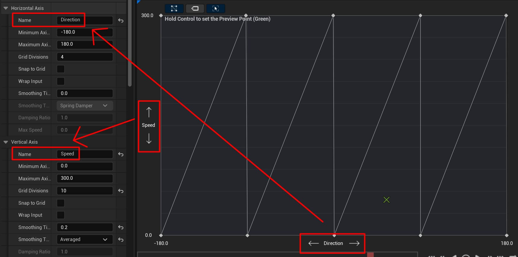
You’ll also notice that the Speed axis has values from 0 to 300 and the Direction axis has values from -180 to 180:
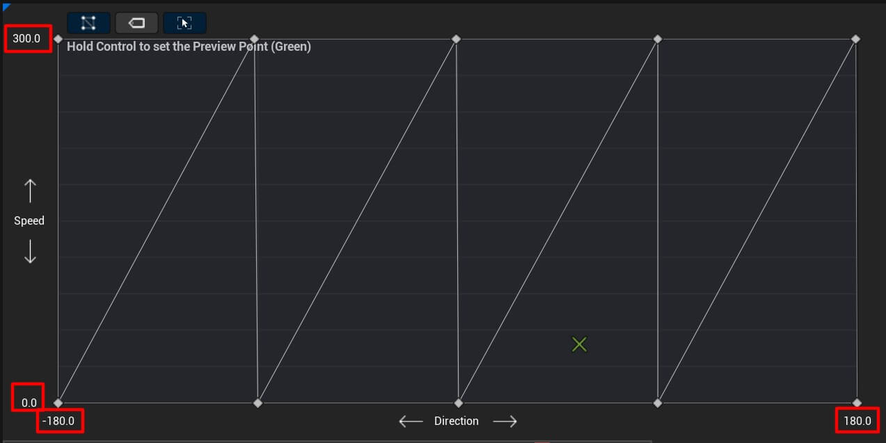
These are the same values we set in the Axis Settings for the appropirate axis:
These values are going to determine which animation is going to be played. If the Speed axis value is at 259 and the Direction axis value is at 155 we’ll play a blend between two animations that intersect at those values.
This is how it looks like when we preview the animation:
Of course, we are going to use character speed and direction when he starts moving in the game and based on those values we’ll play the appropriate animations in the BS_Movement blend space.
Running Blend Space
Create a new blend space and name it BS_Running:

Make sure that you select the appropriate Skeleton for the animation:

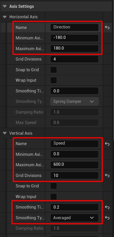
Open BS_Running blend space and for the Axis Settings set the following values:
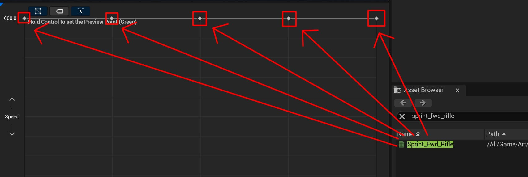
In the Asset Browser search for the sprint_fwd_rifle and drag the animation as you see in the image below:
Next animation is jog_bwd_rifle:
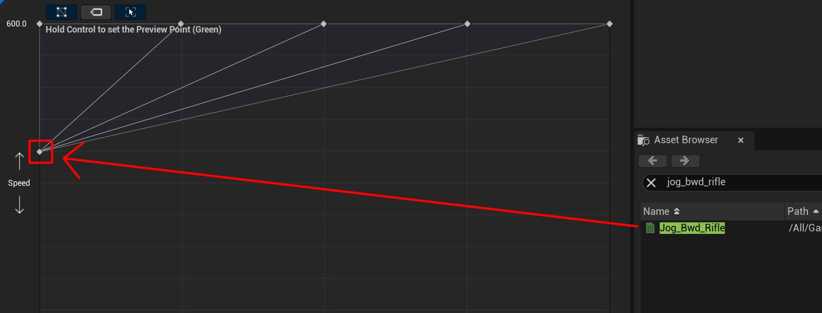
Moving forward we have jog_lt_rifle animation:

Next animation is jog_fwd_rifle:

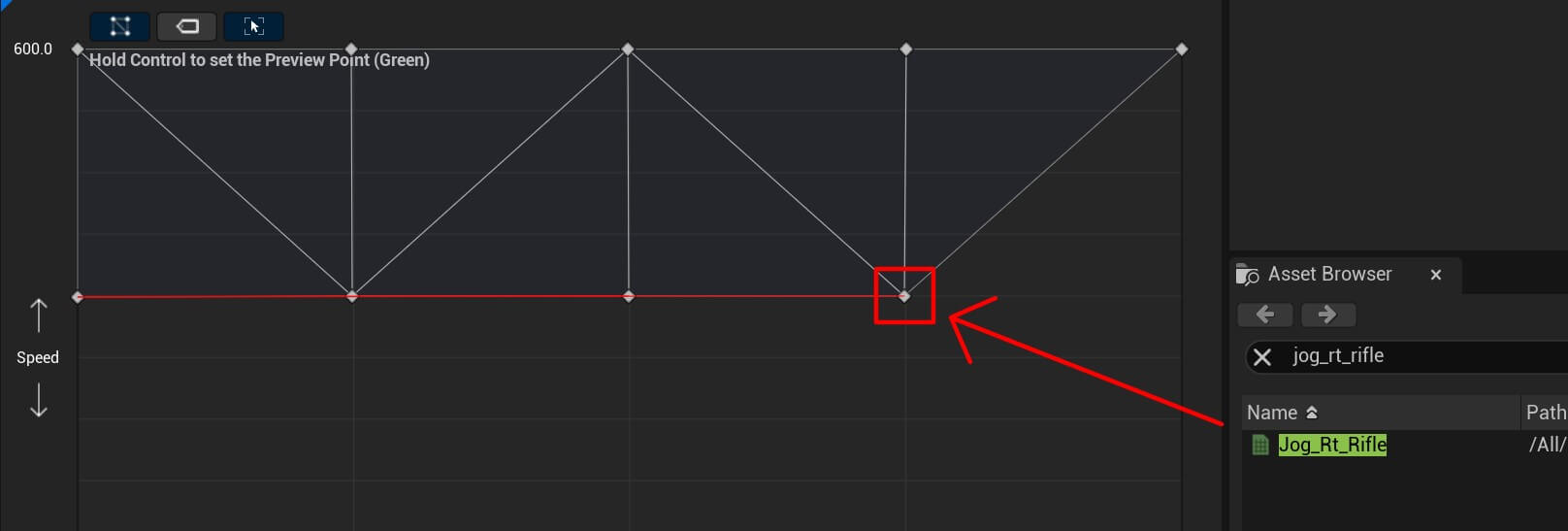
The before last animation jog_rt_rifle:
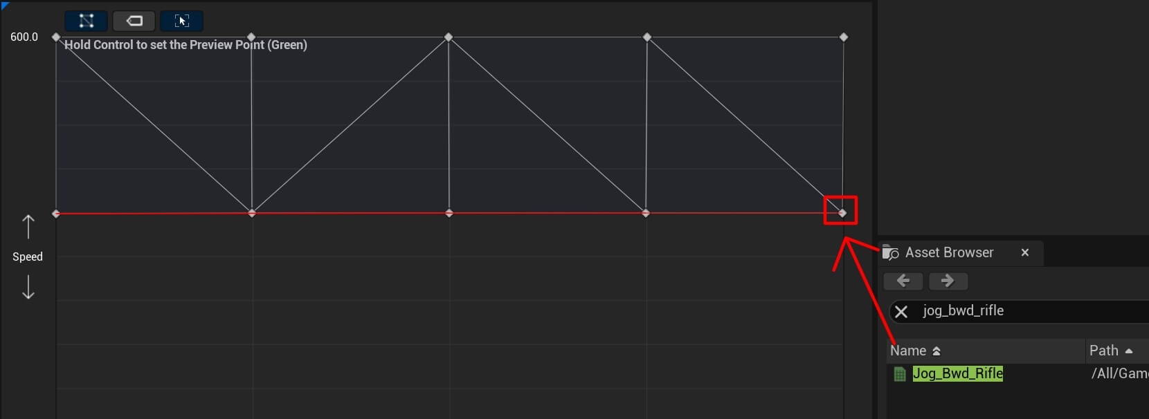
And the last animation is jog_bwd_rifle:
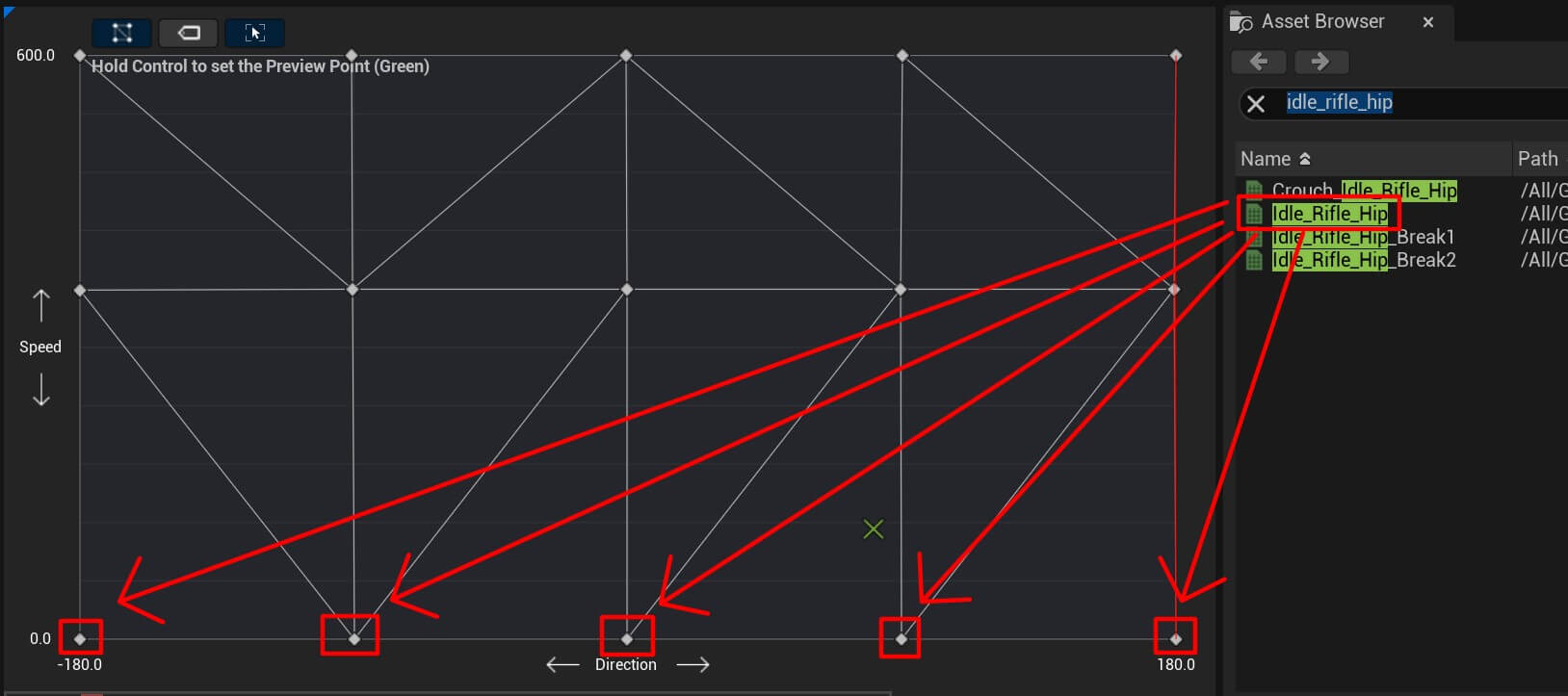
We have one more animation which goes at the bottom. It’s the idle animation called idle_rifle_hip:
Blending BS_Movement And BS_Running Blend Spaces Inside The Player Animation Blueprint
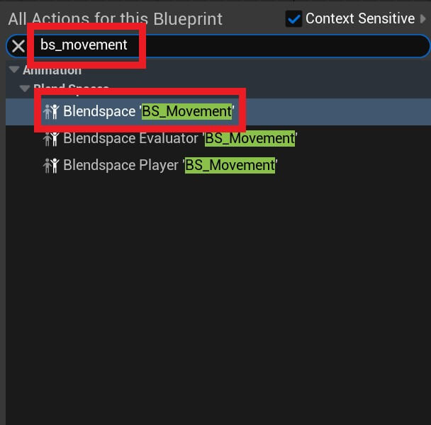
Now open the BP_Player_Animation blueprint and inside the graph for the Idle / Run state Right Click and in the search bar first search for the BS_Movement node:
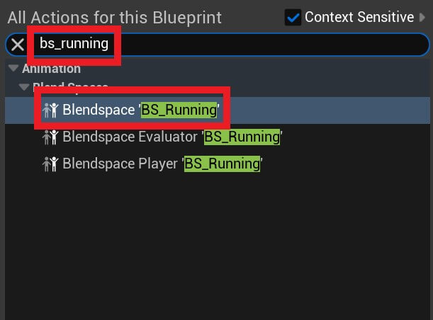
And then for the BS_Running node:
Next, from the Variable tab drag the Direction and Speed variables and plug them in BS_Movement and BS_Running nodes:
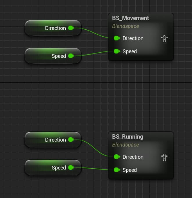
These two nodes are going to play the animations we set in the previous step. But in the game when the player is aiming we are going to walk slower, and when the player is running we are going to walk or move faster.
Because of that, we need to blend these two animations and use the appropriate animation depending on if we are aiming or not.
For that we are going to use blend poses by bool node:
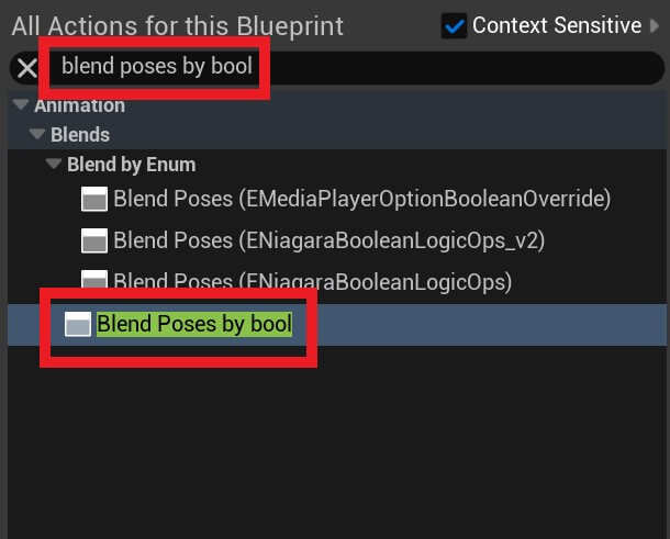
Blend poses by bool takes a bool parameter and based on it’s value, either true or false, it is going to play the appropriate animation.
The bool value which we are going to use as the condition is Aiming Down Sights which we’ll use to inform the blueprint if we are aiming or not:
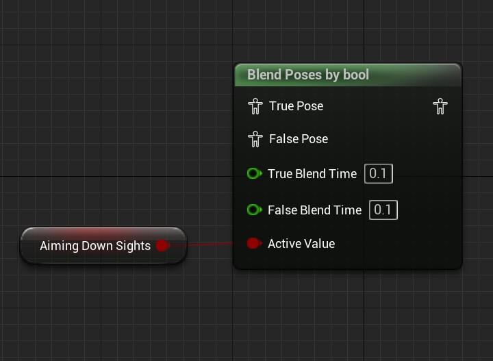
And now we are going to plug the appropriate blend space animations in the true and false output:
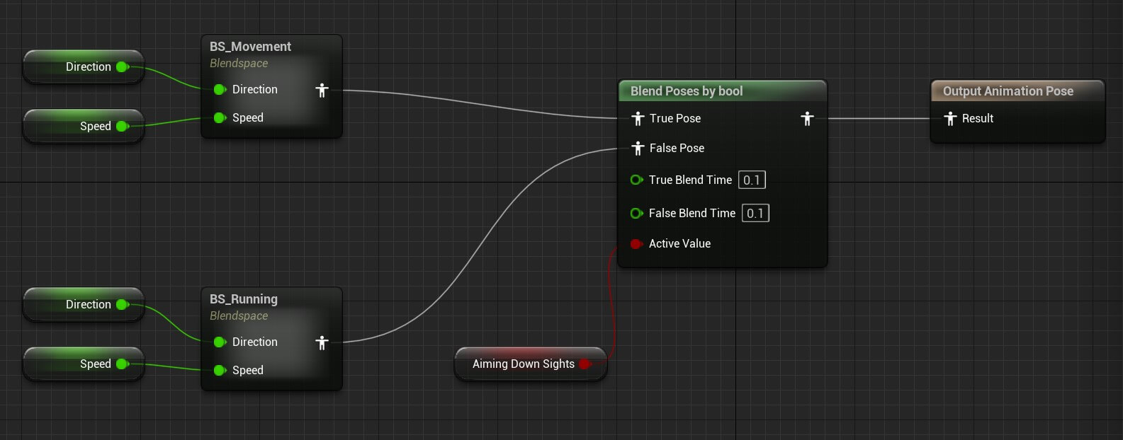
You can copy the nodes from here:
And with this we are done with the Idle / Run state. Next open the Jump Start state by double clicking on it:
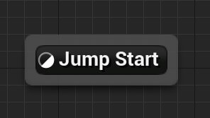
If you don’t know how to navigate the graph editor hierarchy is here:

If you want to navigate back where all the animation states are just click on Default:

You can also watch the guide which will show you how to navigate inside the animation blueprint by clicking here.
Then in the default open the Jump Start state. Inside the Jump Start state in the Asset Browser filter for the thirdpersonjump_start animation, drag it in the editor and then search for the idle_rifle_hip animation and drag it in the graph:
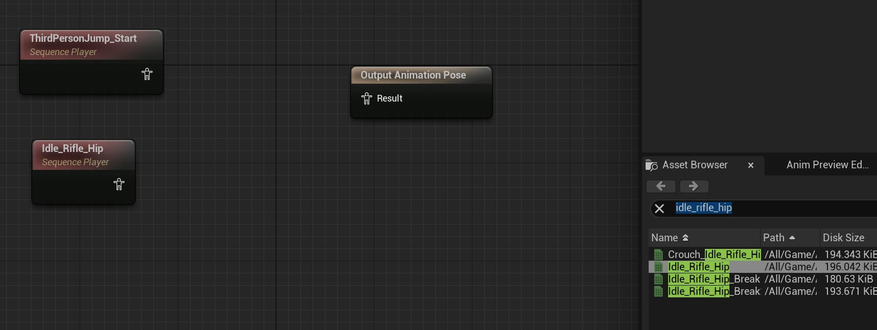
We are going to blend these two animations so that when the player jumps and falls down the jump animation will simply blend into the idle animation and we are going to do that with Layered blend per bone node:
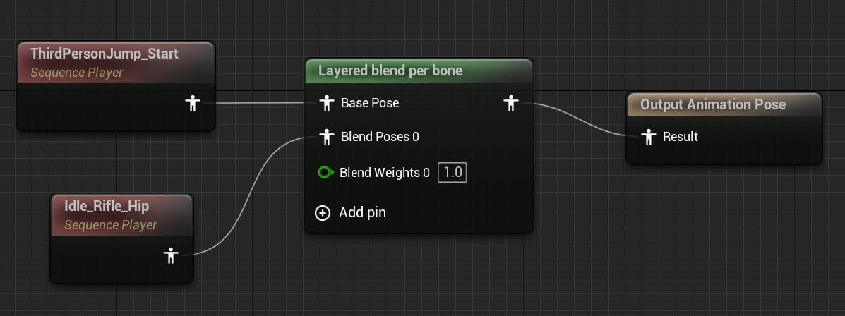
You can copy the nodes from here:
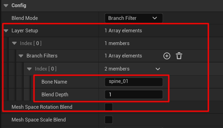
Now to make the Layered blend per bone work, we need to click on it, and in the Details tab click on the Layer Setup -> Index -> Branch Filters then create a new array element and for the Bone Name type spine_01:
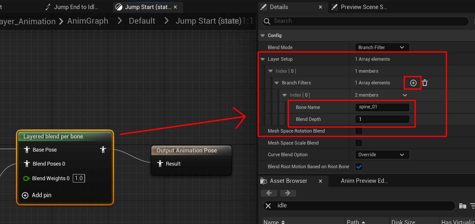
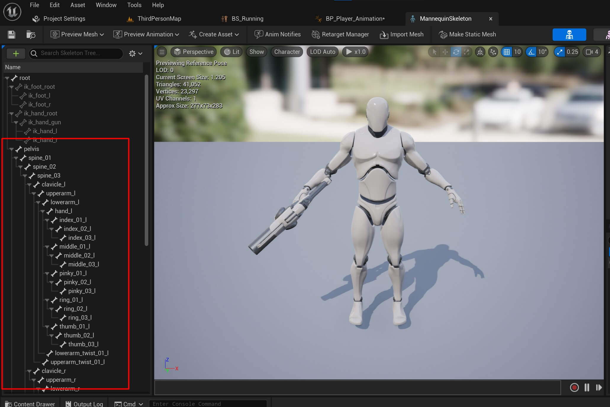
The bone name we passed is important because that’s the base in the skeleton of the 3D model which will be used to blend these animations.
And you can find the bone names by clicking on the skeleton option inside the graph:
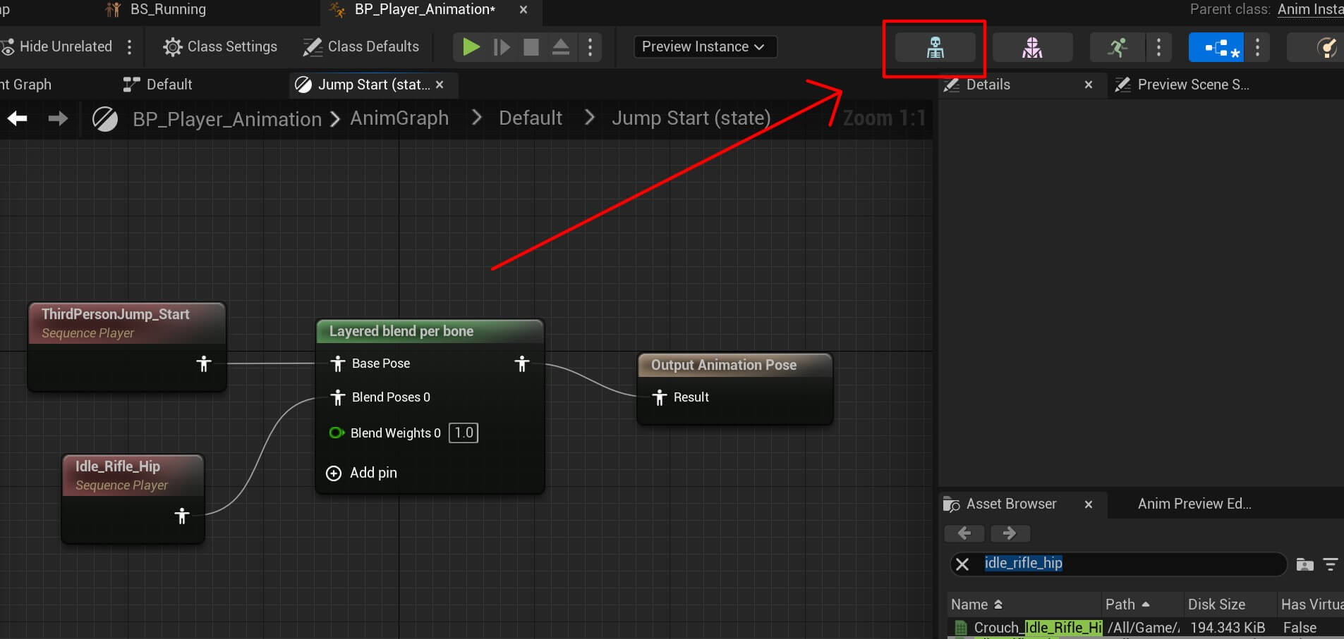
And in the new window the bone names are in the left tab:
Moving forward, for the Jump Idle state we are going to do the same thing for the thirdpersonjump_loop and idle_rifle_hip animations:
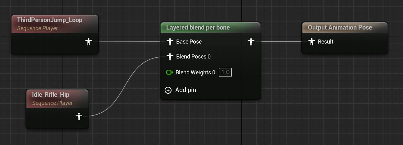
You can copy the nodes from here:
Again do the same thing for the Layered blend per bone and add the spine_01 in the Bone Name field:
Lastly for the Jump End state, we are going to do the same for the thirdperson_jump and idle_rifle_hip animations:
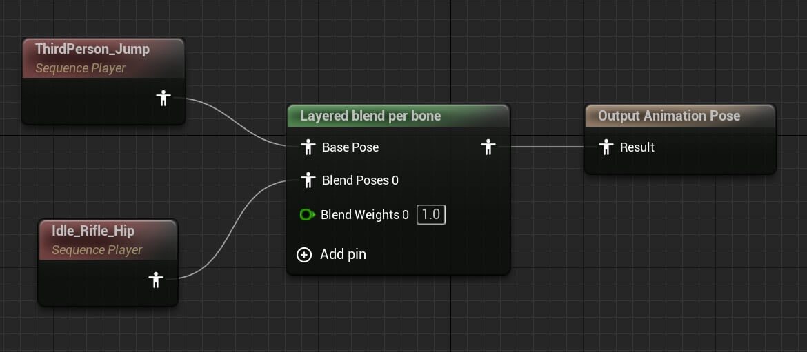
You can copy the nodes from here:
And repeat the process for the Layered blend per bone:

Animation Transition Conditions
To move from one animation state to another we need to create transitions which will indicate the direction of the animations e.g. which animation will be played next.
To create a transition simply drag a line from one state node to another. If you don’t know how you can see in the guide we created in another blog post by clicking here.
So when we jump we are going to go from Idle / Run -> Jump Start -> Jump Loop -> Jump End:
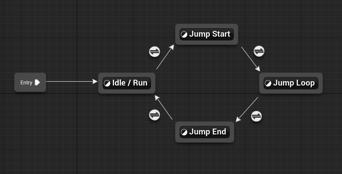
These arrows represent the transition from one animation state to another. But to trigger that transition we need to create a condition that needs to be fulfilled for that to happen.
To create a condition double click on the circle above the transition arrow.
First we are going to create the condition from Idle / Run to Jump Start:
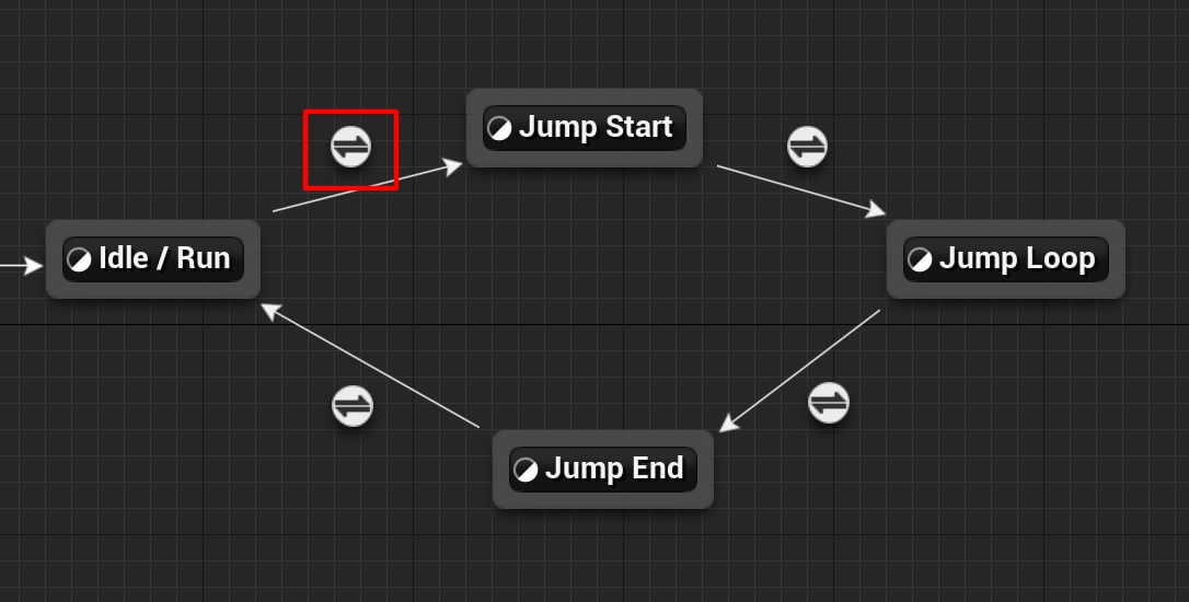
And the condition for this transition is going to the following:
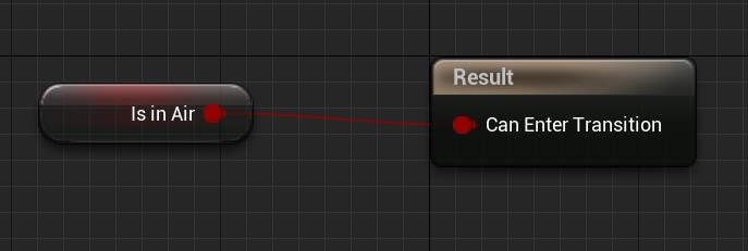
This basically means when the Is In Air variable is true, then the animation will transition from Idle / Run state to the Jump Start state.
Next we are going to set the condition for the transition between Jump Start and Jump Loop state:
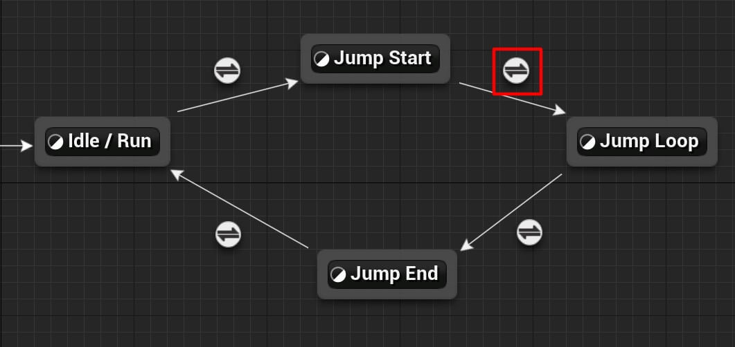
The condition for this transition is going to be the end of the Jump Start animation e.g. when the jump animation finishes playing, we are immediately going to transition to Jump Loop animation.
For that, we need to find the time remaining of the playing animation so Right Click and in the search bar type time remaining third person jump start and select the function you see in the image:
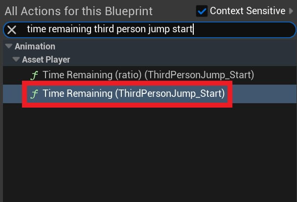
We are going to compare the returned value to a float to determine when the animation has finished playing. So drag a line from the returning value and in the search bar type < and then select less:
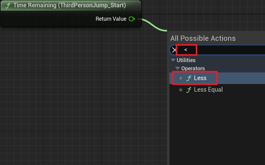
For the float value to which we are comparing we are going to put 0.1 and then plugin the returned bool value in the result:

This means when the ThirdPersonJump_Start animation play time gets to a value that’s less than 0.1 then this condition will be true and we will transition to the next animation.
The next transition is the one between Jump Loop and Jump End:
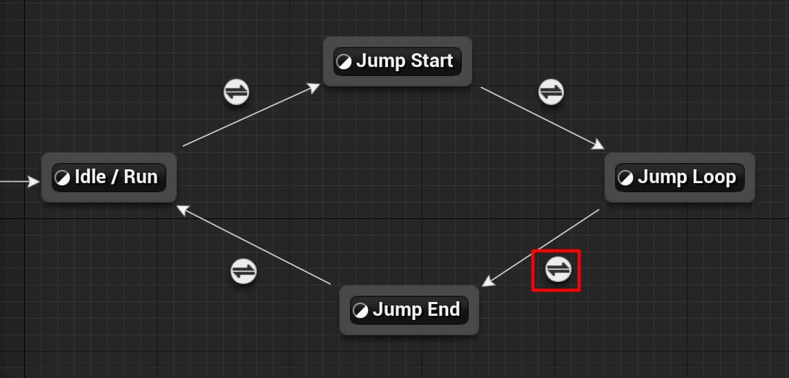
And the condition for this transition is the following:

We are testing the opposite of Is In Air basically we’re asking if we are not in the air, then we are going to play the Jump End animation.
And the last transition is from Jump End to Idle / Run:
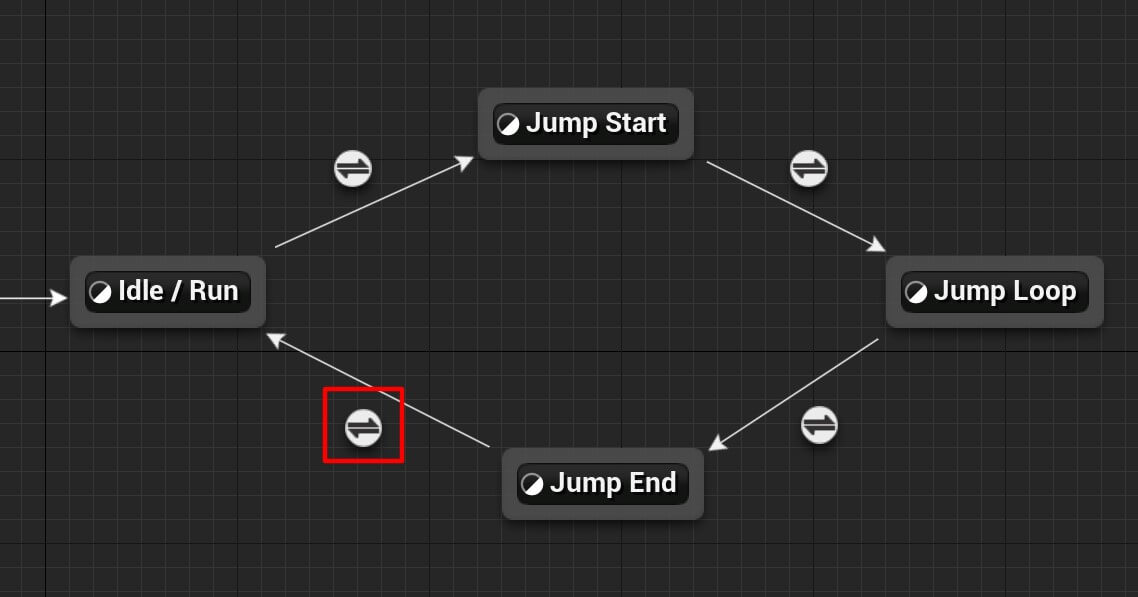
The condition for the last transition is going the following:

The logic is the same as the one in the condition for the transition between the Jump Start and Jump Loop, except here we are testing when the jump animation playing time gest to the value which is less than 0.1 then the condition will be true and we will transition to the Idle / Run animation.
Playing The Character Movement Animation
Before we can test the player’s animations we need to pass all the parameter values which we set in the conditions for the transitions.
As well as the Speed and Direction variables which we’re using as conditions for the movement animation.
Go in the Event Graph tab in the BP_Player_Animation blueprint, then from the Try Get Pawn Owner node drag a line and in the search bar type is valid and select the one with the question mark:
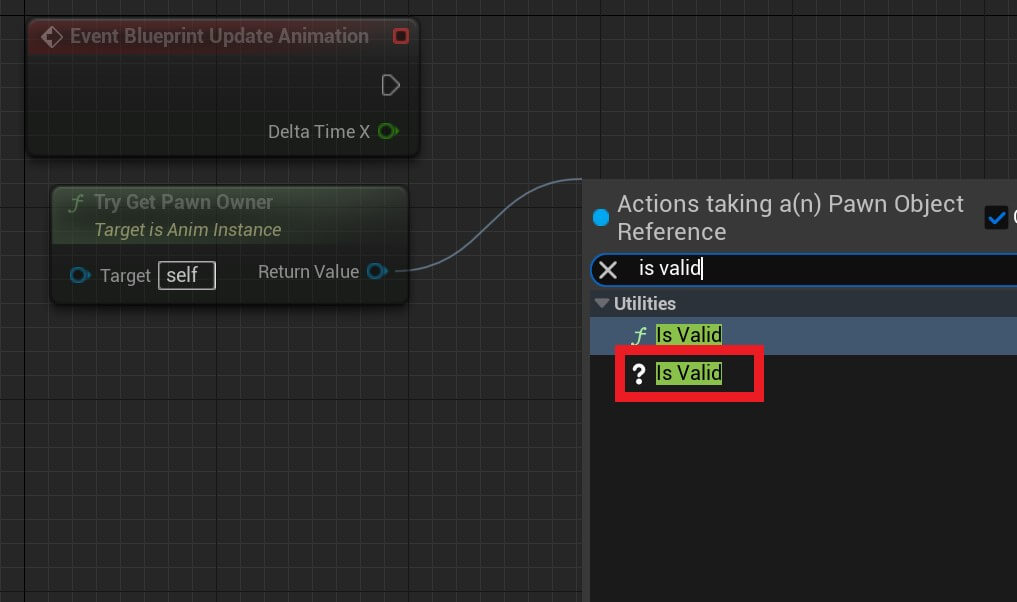
This is going to test if the pawn owner or if the animation blueprint has an owner meaning the animation blueprint is being used on an actor.
If that is true, we’re going to test if the character is in air:
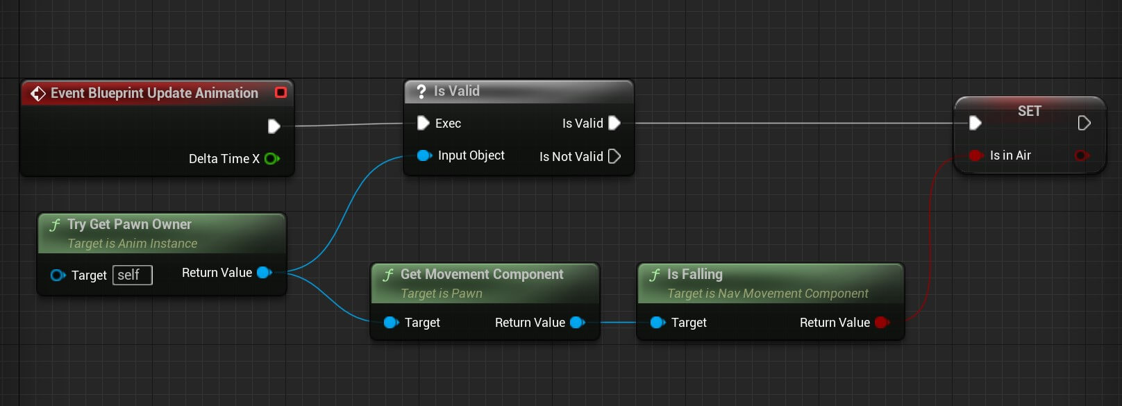
To test if the character is in air we simply get the movement component from the pawn owner because we know we have that component attached on the character since we inherited from the Character class.
Next we are going to set the value for the Direction variable:
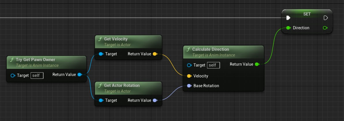
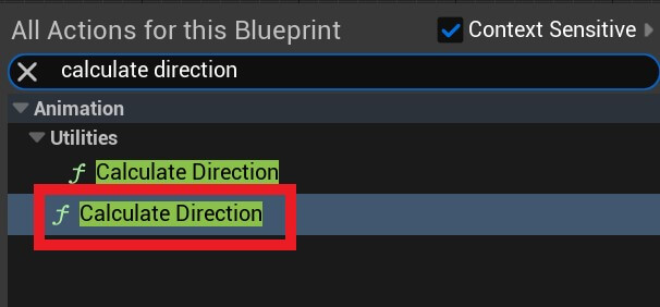
When you’re searching for the calculate direction node make sure that you select the one which has 3 parameters:
After that we’re going to calculate the speed:

The speed is calculated by using the length property of the velocity vector for the character movement because the velocity represents the speed of the character movement and the leght of the velocity is the speed value.
Moving forward we are going to set the value of the aiming down sights variable.
For that, in the Begin Play node we’re going to get a reference to the BP_Player object:

Now that we have a reference to the player object we can set the aiming down sigths variable:

You can copy the nodes we created so far from here:
Before we proceed, you’ll have an assignment to rewrite the current code and make it better.
While this code will run fine and there are no performance issues, there is a way to write it better and have better performance in a potentially larger game.
One hit we’ll give you is look at the variables we’re setting and from where we are setting them. This will help you figure out how to write the code better.
And if you can’t figure out what you need to do, leave a comment below and we’ll help you out.
This is a method we’re using inside Game Dev Pro which we found very effective because the best way to learn is by doing and by doing we don’t mean just copy-paste what’s being done in the tutorial you’re following but changing stuff in the project, rewriting the code and so on.
In Game Dev Pro we challenge our students all the time to finish assignments, come up with better ways to write the code, optimize the game and so on. Of course, we provide the solution, but the students learn through the experience of trying to fix the issue on their own.
That’s one of the reasons why we’re able to help thousands of people become pro game developers and get hired in the best game studios in the world and why we have thousands of people who did just that.
And that’s why Game Dev Pro can help you do the same. You can check it out by clicking on the link here: Game Dev Pro
Next we are going to set the pitch, and for that we are going to create a function. In the Functions tab on the left side create a new function and call it SetPitch:

In the SetPitch function add the following code:
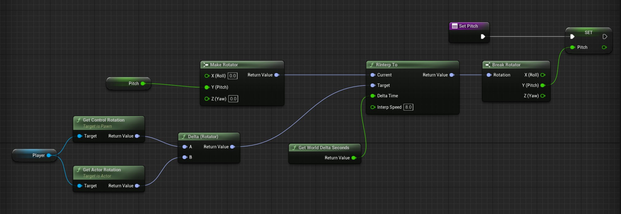
You can copy the nodes from here:
First we get the values of the control rotation and the actor rotation and we’re merging them together inside the Delta Rotation node. Btw, the control rotation is the rotation of the controller of our player character and the actor rotation is the rotation of the player character himself.
Then we created a new rotator by passing the current value of our pitch variable and we used RInterp To node to interpolate from the rotator we created using our pitch variable, and the rotator created from the Delta node where we passed the control rotation and actor rotation.
The interpolation will move from the current rotator to the target rotator e.g. the values of the parameter we pass in the current to the values of the parameter we pass in the target.
Essentially it is going to set the values of the current rotator to the same values of the target rotator in the time we passed e.g. delta seconds with the speed we passed in the Interp Speed parameter.
When we calculate those values we break the rotator again and we use it’s pitch value to set the value of our pitch variable.
Now that we have the SetPitch function we can move forward with the code:

You can copy the final nodes before we test the player animation from here:
After we called the SetPitch function which is going to set the pitch as we explained a moment ago, we’re setting the Sprinting bool variable by testing if the character movement max walk speed is greater than the walk speed.
We have everything we need to test the character movement animation but before we do that, inside the BP_Player_Animation blueprint in the AnimGraph connect the Default state machine with the output pose:
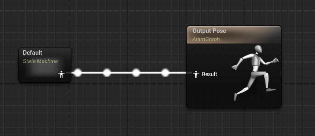
Inside the BP_Player blueprint select the mesh component and in the anim class select BP_Player_Animation:

When we play the game this is how the animation looks like:
Every time we pressed the Left Shift key the player character started sprinting and we saw the animations being played.
These animations are controlled by the Direction and Speed variables that we set in the BP_Player_Animation EventGraph which we already explained and the values we set in that graph will be the values that the Idle / Run state is using to play the BS_Movement and BS_Running animations:
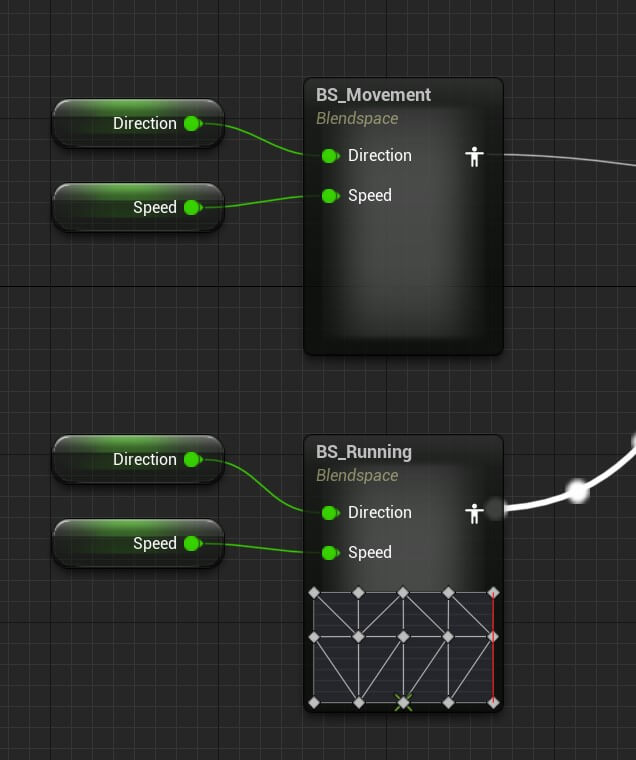
The transitions for all animations work in the same way. We set the values for the variables such as is in air and sprinting and when the values change the transitions for the appropriate animations will trigger.
Before we proceed, if you followed every step up to this point, when you test the player movement animations you’ll probably get an error like this:

Your assignment is to fix the error before you proceed. Of course, we’re going to provide the solution, but agian, the best way to learn is by practice, and you learn the most when you practice solving bugs.
Below you’ll find the nodes which you can copy paste in your project and compare with the current setup and you’ll see the key difference, which is very small btw, that will make that error go away.
But we highly encourage you to try and solve the problem on your own before you copy and paste the nodes.
Creating The Character's Aim Offset Animation
Inside the Player_Character folder create a new folder and name it Aim_Offsets. Inside the Aim_Offsets folder Right Click -> Animation -> Aim Offset:
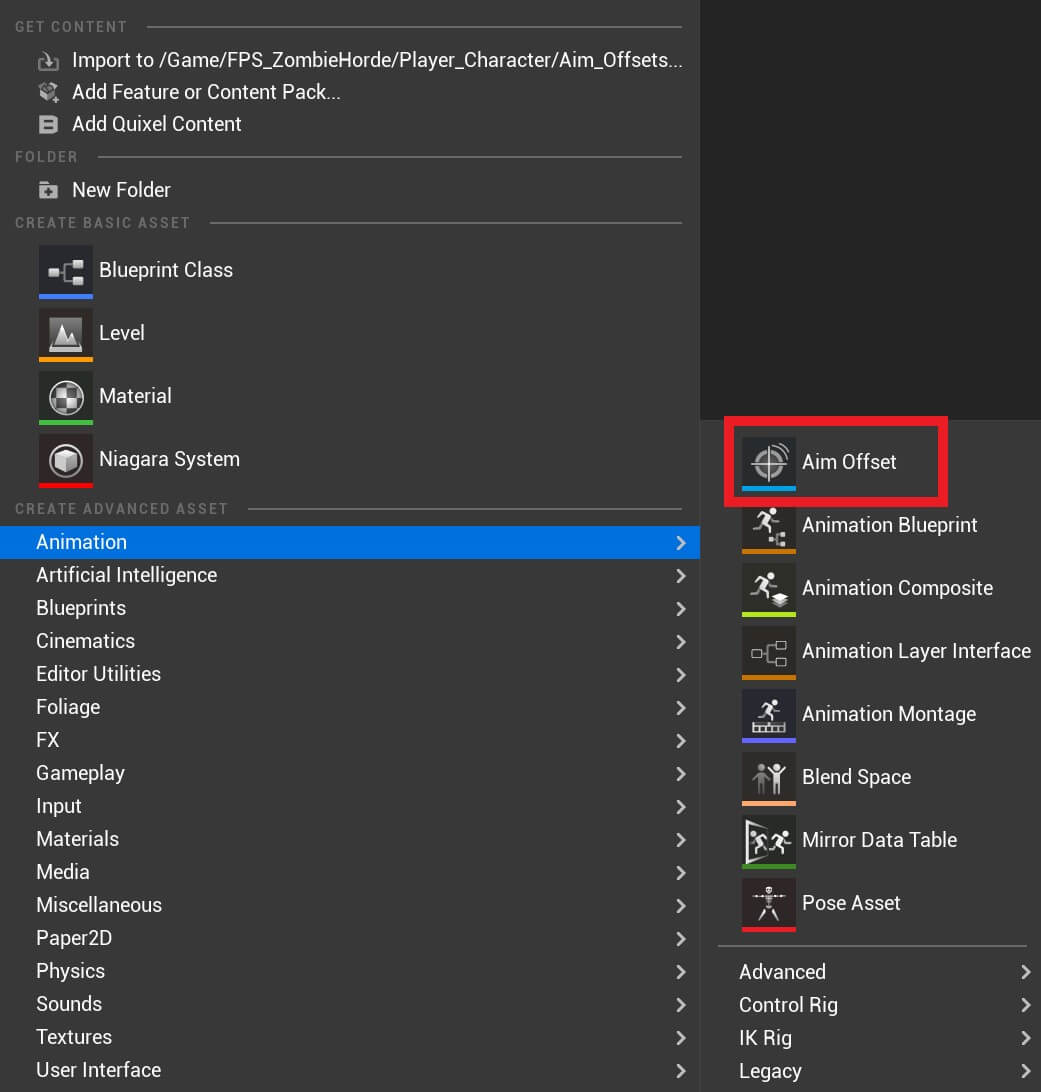
In the next window select the appropriate skeleton for the animation which is the same player character skeleton we used for the animations so far:
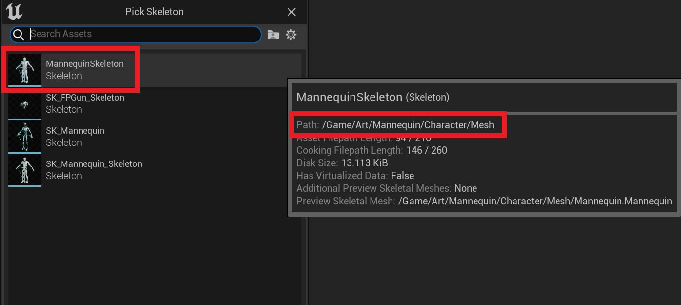
Give the aim offset animation name Aim_Offset_Movement and open it in the editor.
Before we proceed, an aim offset animation is used to create a multidimensional weapon aiming blend structure or to put it in simple words it is going to allow us to play aiming animations and walking animations at the same time.
Moving forward, in the Asset Details tab on the left side under the Axis Settings then Horizontal Axis add the following values:
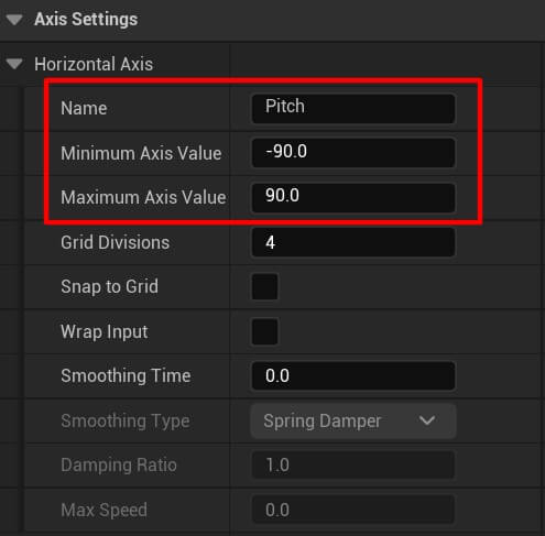
We’re not going to change the values of the vertical axis because we’re not going to use it.
Next, in the Asset Browser type is_cd and drag the animation at the same place like in the image below:
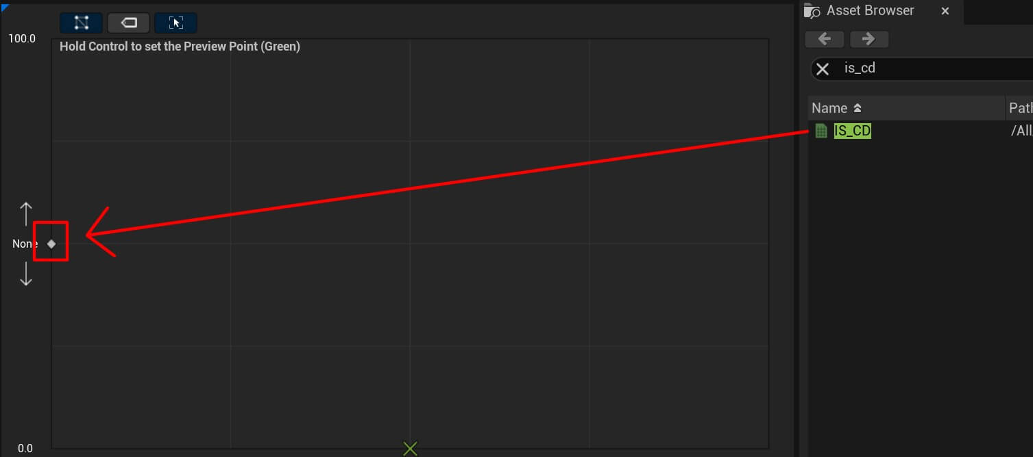
Moving forward the next animation is is_cc and it goes here:
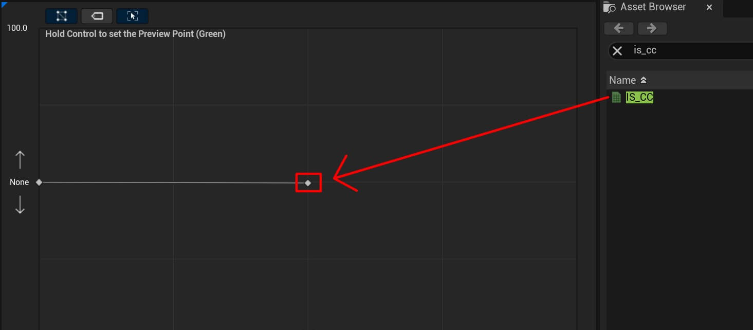
And the last animation is is_cu which goes here:
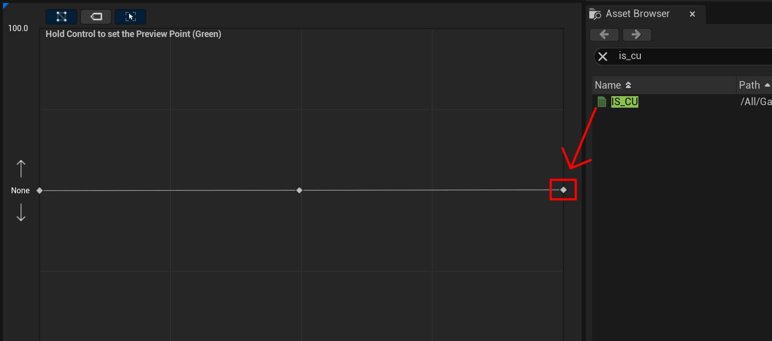
If you try to preview the animation and it looks wierd, you just need to remove the preview base pose:
Now we’re going to create another aim offset for the idle animation. So repeat the same process to create the aim offset and name it Aim_Offset_Idle. Open the Aim_Offset_Idle and in the Axis Settings for the Horizontal Axis add the following values:
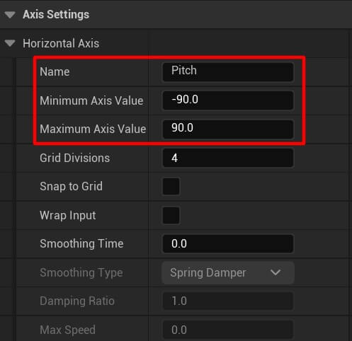
Again we’re not going to use the Vertical axis so we’re not going to edit its settings.
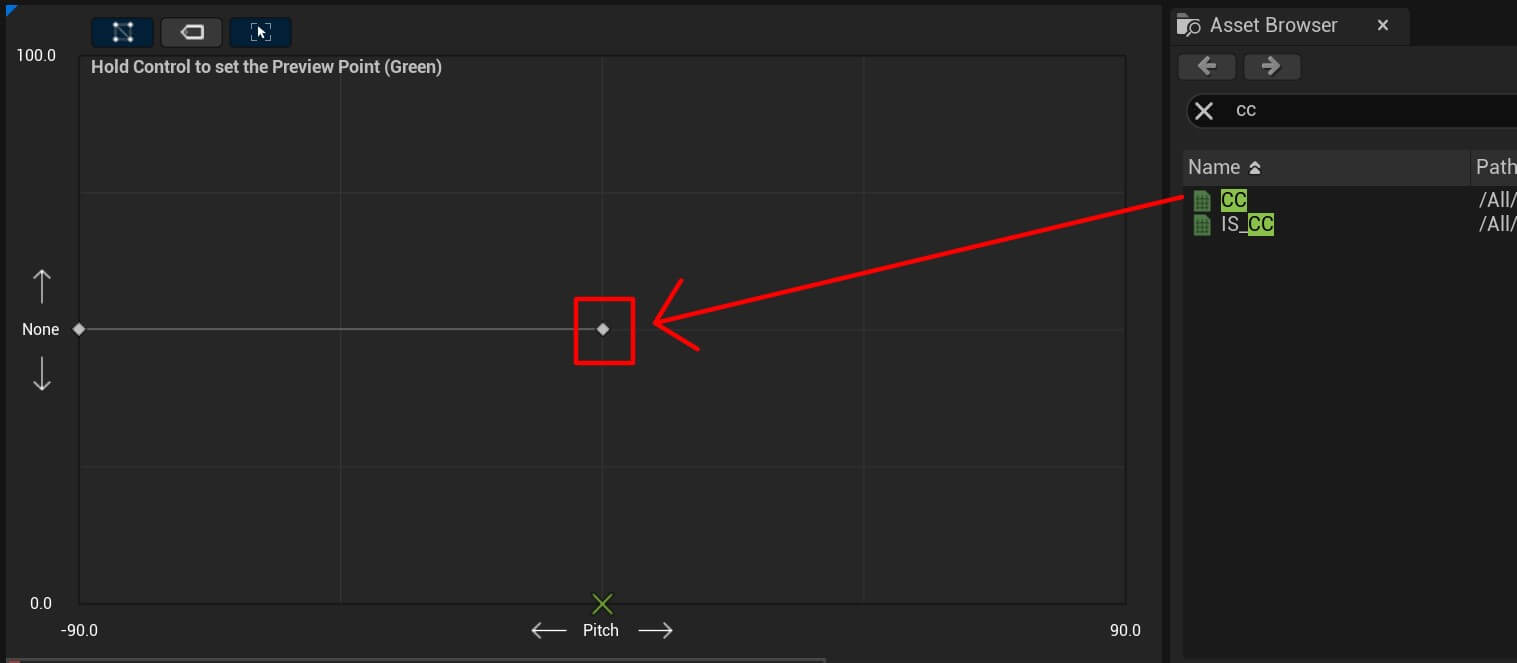
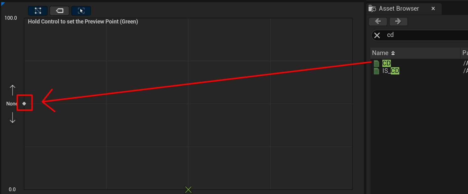
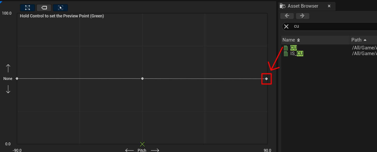
We’re going to add the following animations in the appropraite places like in the images below.
Starting with cc:
Then cd:
And finally cu:
Now open BP_Player_Animation AnimGraph. Right Click the type in the search save cached pose:
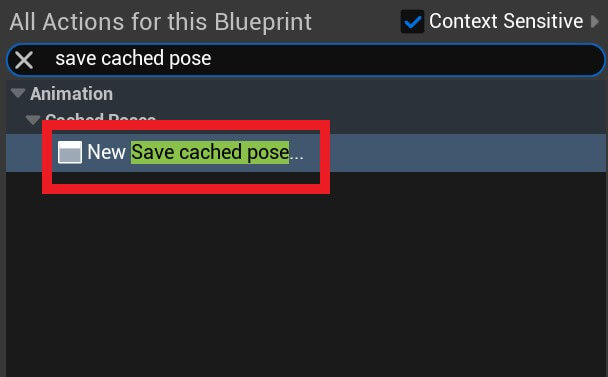
We’re going to cache the movement animation in the new node we created and then combie it with the aim offset animations.
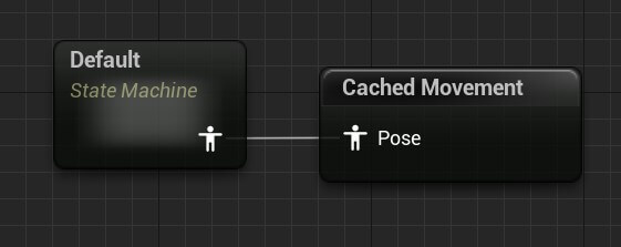
So disconect the default state machine node from the output pose and connect it to the new cached node we created which you’ll name Cached Movement:
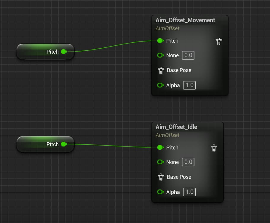
Next, Right Click and in the search bar find the aim offset movement and aim offset idle, and take the Pitch variable and plug it in the appropriate slot for both aim offset nodes:
Now Right Click and search for blend poses by bool:
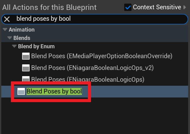
And the bool parameter we’re going to use is the AimingDownSights:
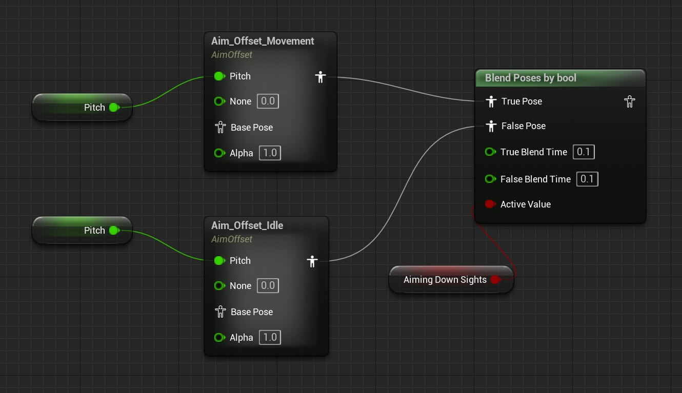
So if we are aiming we’re going to play the aim offset movement animation and if we’re not moving we’re going to play the aim offset idle animation.
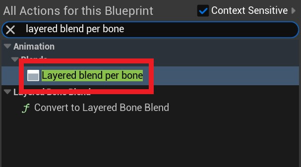
Next, Right Click and search for layered blend per bone:
Now Right Click and search for the cached movement:
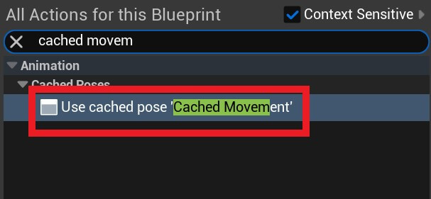
Because we are caching hte movement animation we can use it in a separate node, and we are going to use it as a base pose for the layered blend per bone:
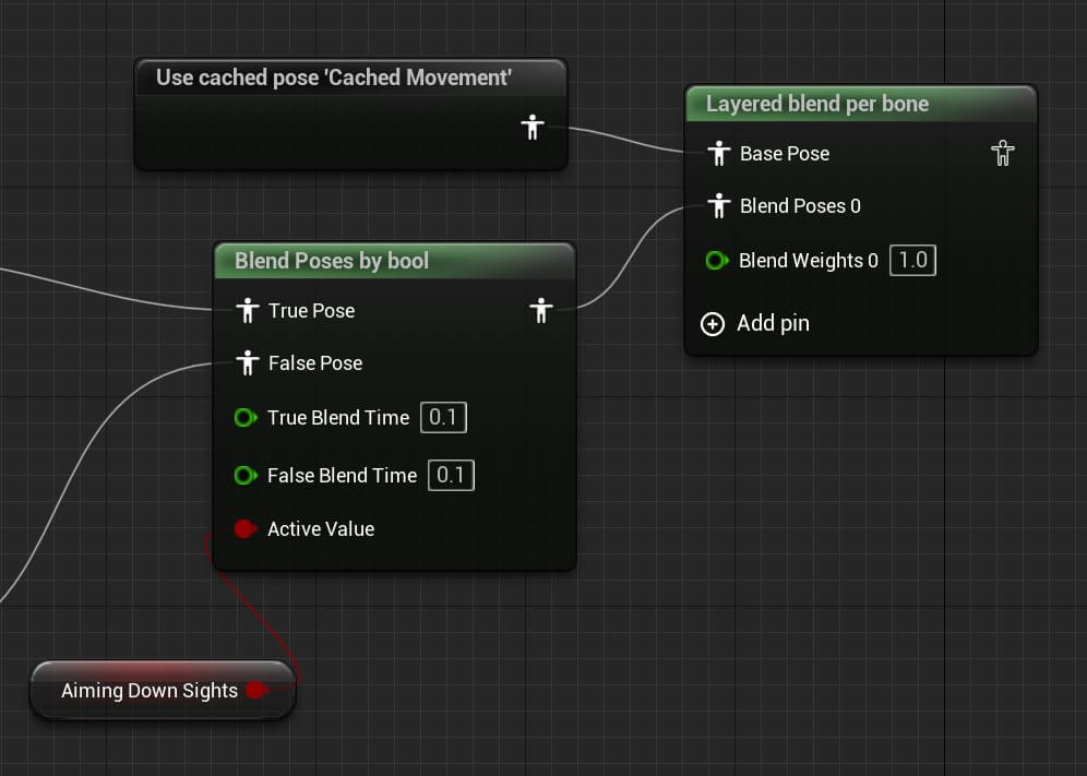
Next select the layered blend per pone and in the Details tab for the layer setup set the following settings:
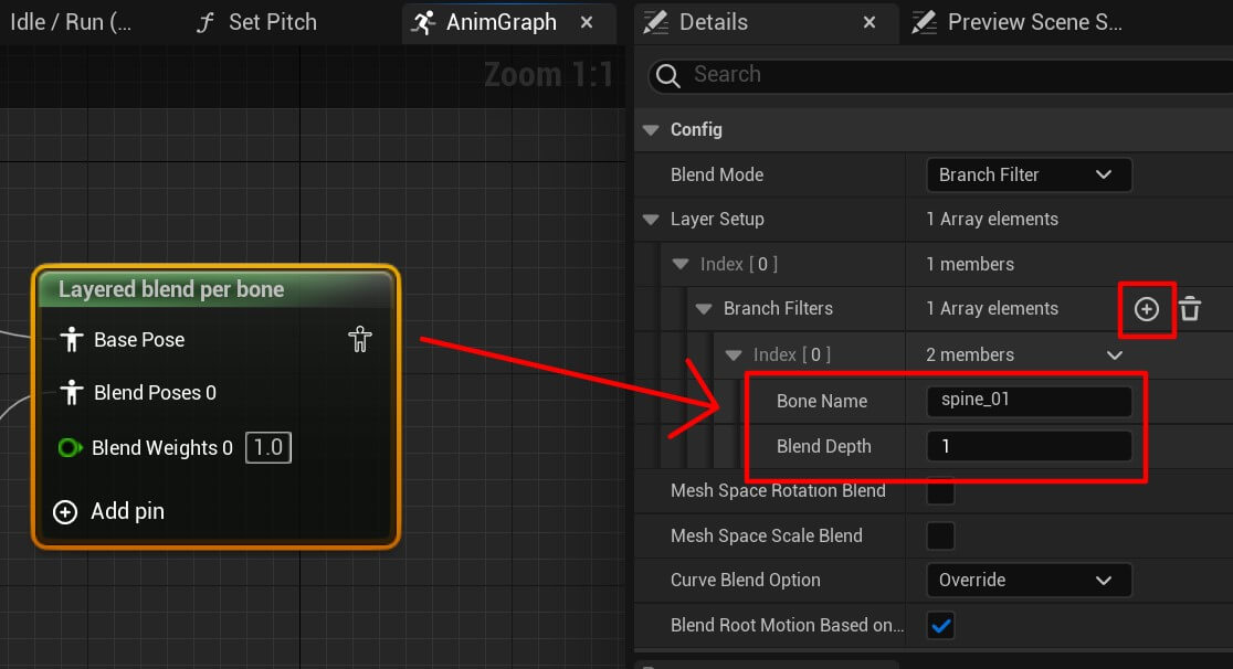
This will indicate where on the animation skeleton this blend will happen.
Create another blend poses by bool and this time we’re going to test if we are sprinting so that we can set the appropriate animations to play:
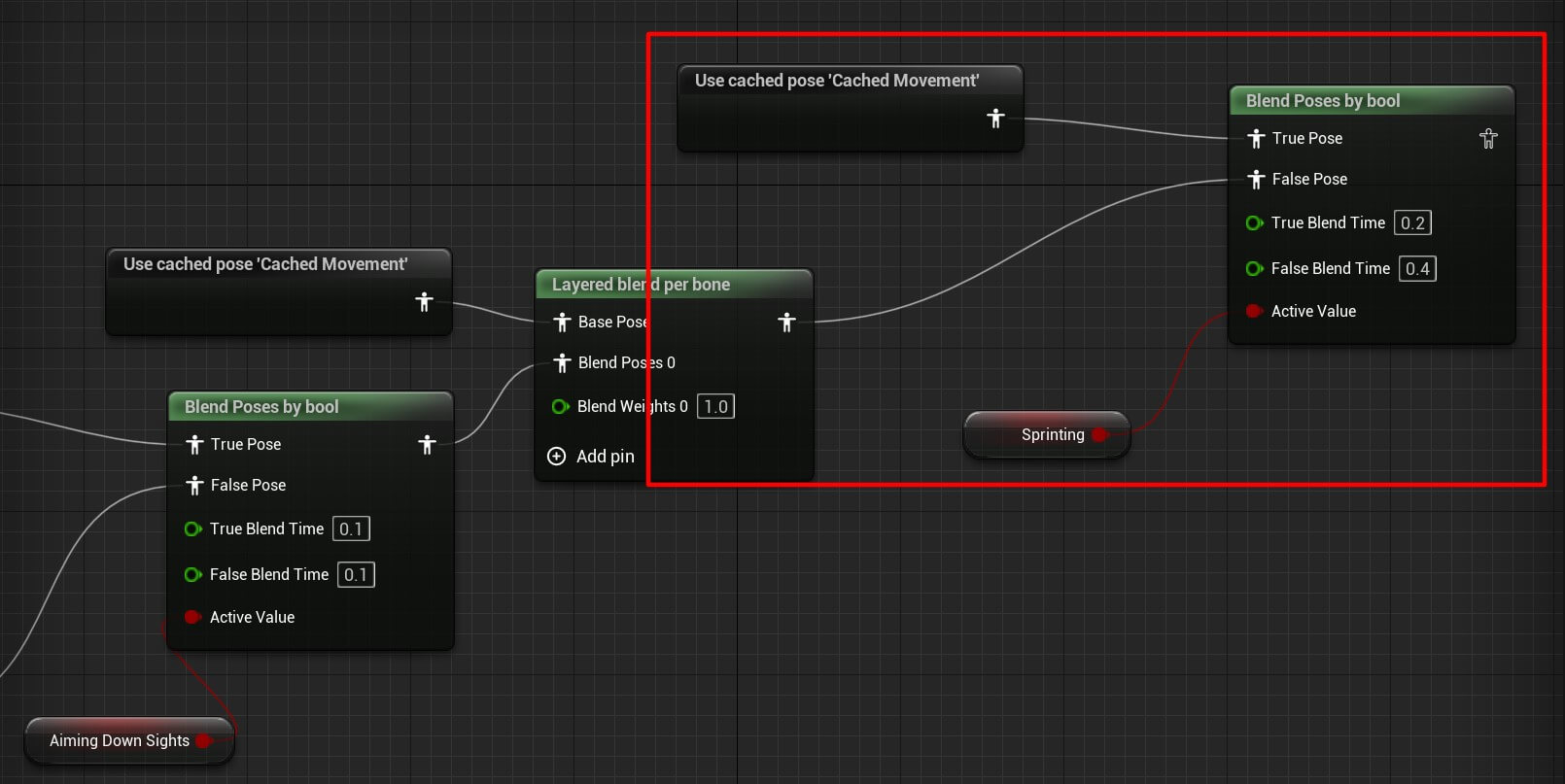
If we are sprinting we’ll use the cached movement for the movement animation, if we are not sprinting then we’ll use previous layered blend per bone we created.
You’ll also notice that we changed the values for the true and false blend time which basically represents how long the blend of the animations is going to last for the true and false blend inputs.
Now create a new save cached pose, name it cached aim offset and plug in the last blend poses by bool we created:
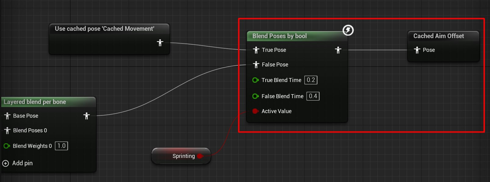
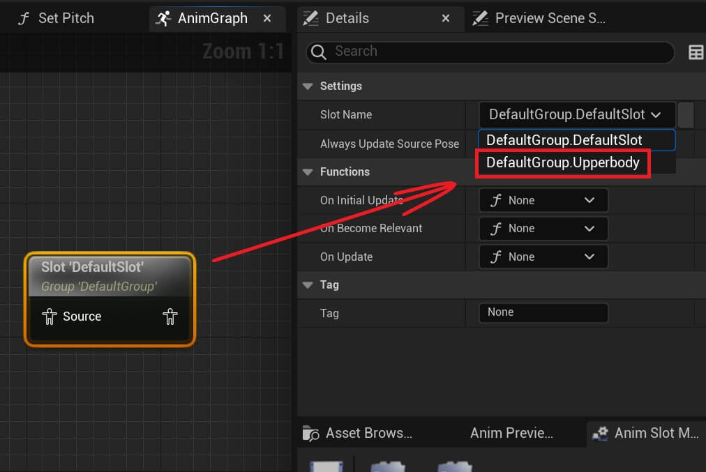
Finally we need to blend the caches we created to make our animations work together. For that first we’re going to create a default slot:
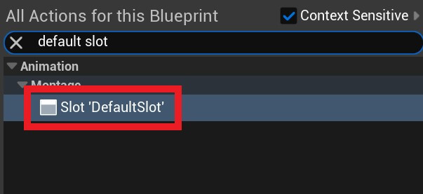
Click on the default slot and in the Details tab for the slot name click the drop-down list and select DefaultGroup.Upperbody:
Now create a layered blend per bone node and two cached aim offset nodes and plug them according to the image below:
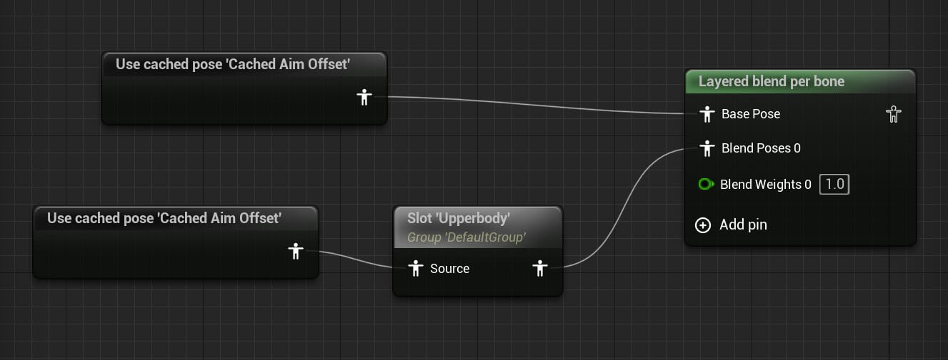
One cached aim offset is going to affect the upper body through the default slot and the other is going to affect the lower body.
We also need to change the settings for the layered blend per bone:
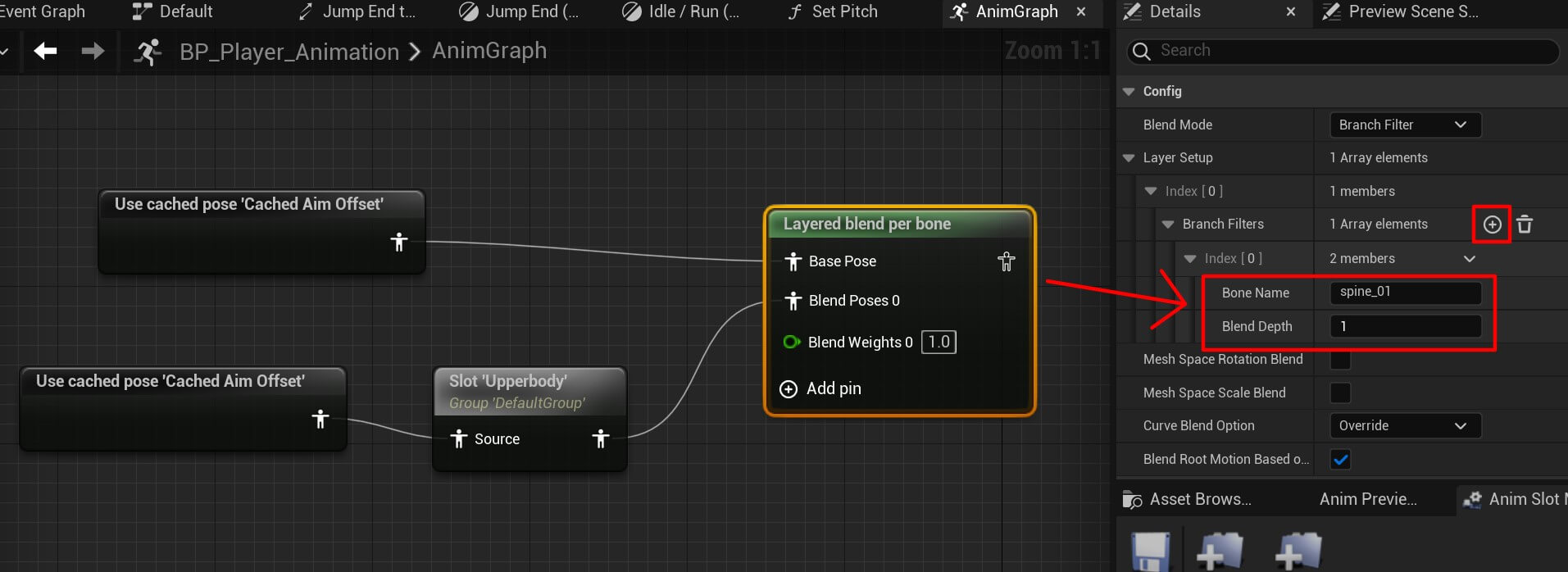
Finally, we need to create another default slot and plugin the output of the previous layered blend per bone and plug the output from the default slot in the output pose node:

You can copy the final node structure from here:
Attaching The Gun On The Player Character
Before we can test the animation setup we just created we need to implement the aiming functionality. But first, we need to attach the gun to the player character.
Open the BP_Player blueprint and in the Components tab select the mesh component and from the Add button search for Skeletal Mesh:
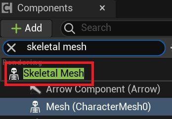
Give the skeletal mesh name Gun, select it and in the Details tab for the Skeletal Mesh select the SK_FPGun:
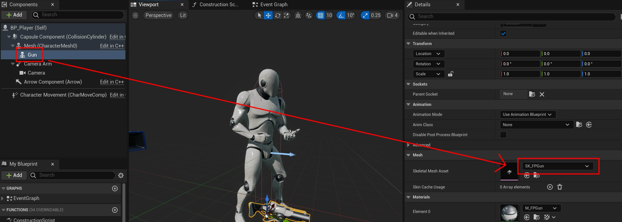
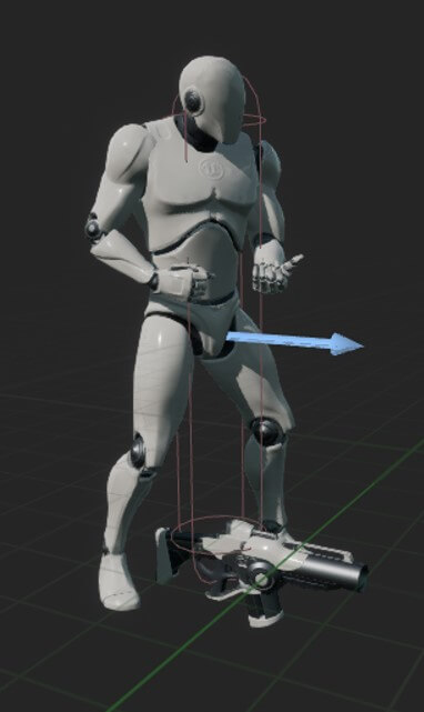
The gun is added to the character but it’s located on the feet of the character:
To place it in the hands of the character we need to select the gun skeletal component, and in the Detals tab for the Sockets click on the folder icon and search for the weapon socket:
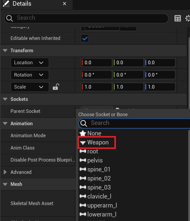
The weapon socket is defined in the skeletal part of the 3D character model and it’s basically a part of the 3D model with the name weapon.
This is how we add items to 3D models and create the effect of carrying a weapon, a backpack, or something else. And that’s how all games add items to the game characters.
We cover that more in depth in Game Dev Pro Rapid Launch which is an advanced course that only those who enrolled in Game Dev Pro can have access to.
If you want to skyrocket your game dev career and you’re enrolled in Game Dev Pro, send us a message and we’ll give you the link to Rapid Launch, if not you can always enrol in Game Dev Pro by clicking on the link here.
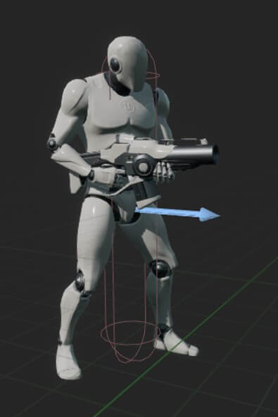
Now that you selected the weapon socket, the weapon is located in the hands of the character:
Before we preview the animations we’re going to add a muzzle or an actor object and position him where the gun’s muzzle is going to show.
For that, select the gun skeletal component and from the Add button search for the scene component:
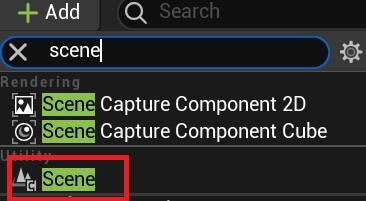
Rename the added scene component to Muzzle, then select it and in the Details tab for the Transform component add the following values:
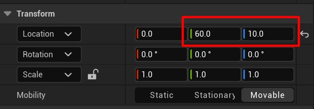
This is going to position the muzzle actor right in front of the gun where the muzzle fx is going to show:
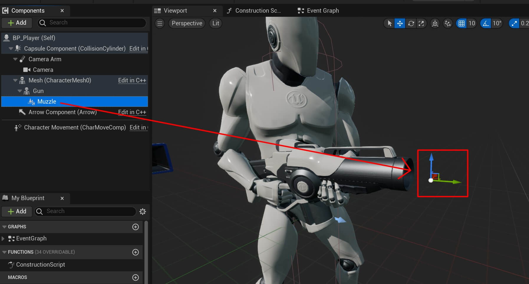
Now we can preview the animations with the player holding the gun and you’ll see how the animations blend together:
Player Aiming Functionality
To create the aiming funcitonality we first need to create an input action.
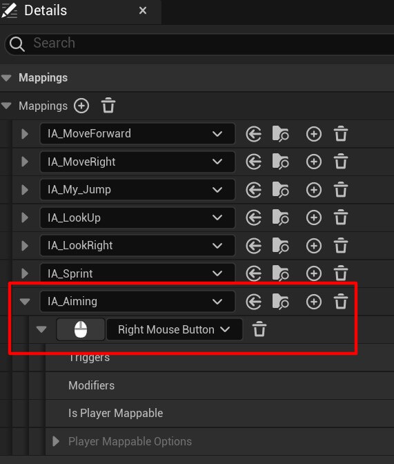
Your assingment is to create an input action that will be triggered with the right mouse button. We already done that so you have a guide but we would love if you try to do that on your own.
So inside the Input folder create a new input action:

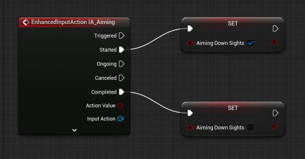
Name it IA_Aiming and add it in the IMC_MovementAndLook:
Inside EventGraph of the BP_Player add the following nodes:
Next we are going to create a new macro and call it Sprinting:
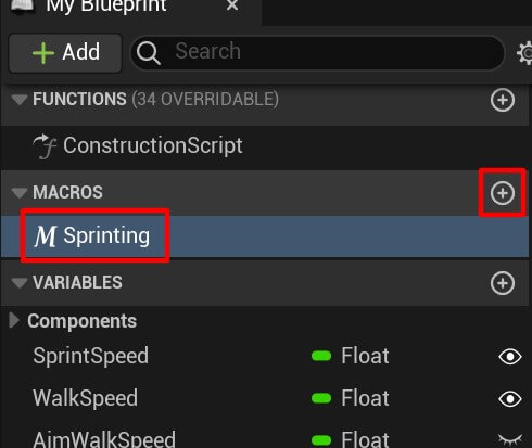
You can think of a macro as a function we can reuse. Select the output node inside the Sprinting macro and create a bool return value and name it Is Sprinting:
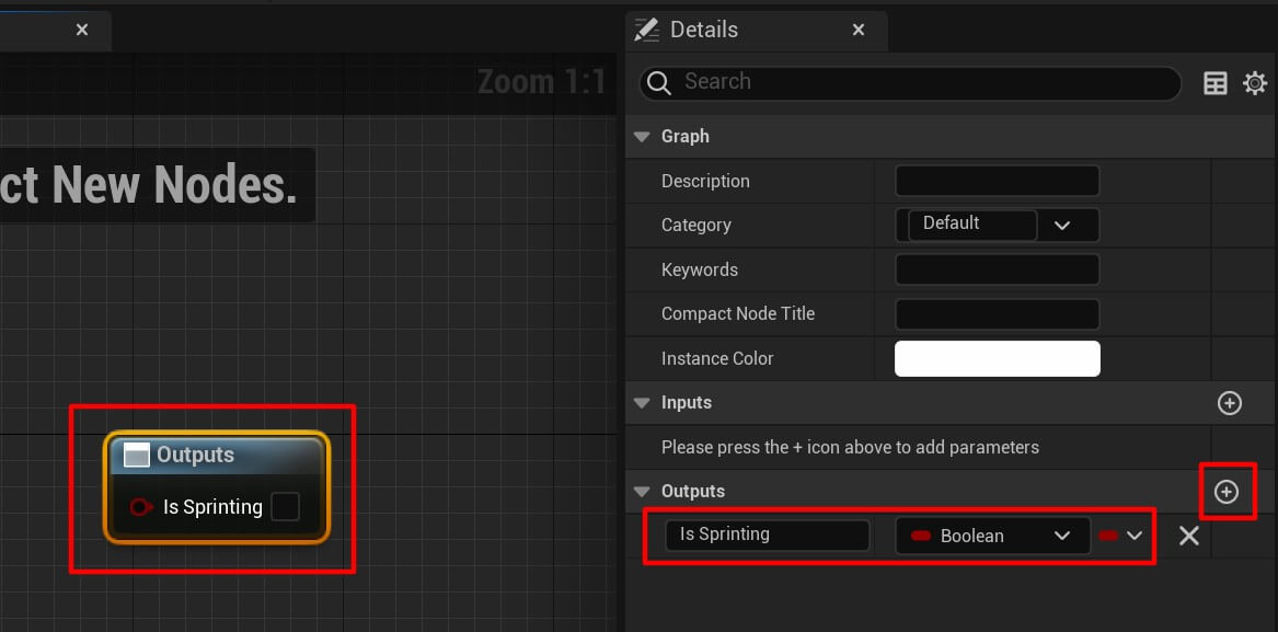
We’re going to use character movement to calculate if we are sprinting or not:

So if the character’s movement max walk speed is greated than 500 we’ll return true – meaning the player is sprinting.
And we’re going to use this macro to set the max walk speed of the character’s movement when the character starts aiming:
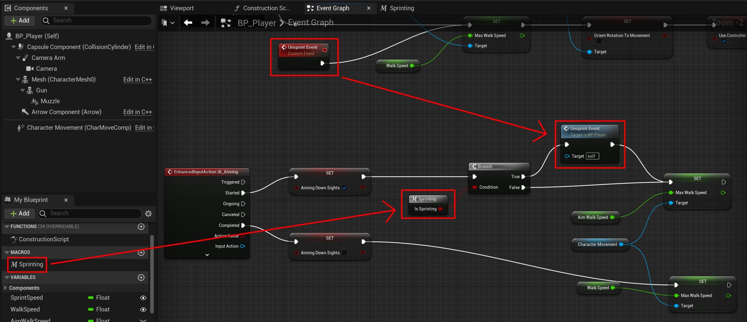
When the aiming down sights is true, we’ll call the macro we created to test if we are sprinting, if that’s true then we call the unsprint event which we created a few steps ago which is going to reset the rotation chages we made.
Then we simply set the max walk speed to aiming speed because we’re going to slowdown the character when he’s aiming.
And when we release the right mouse button e.g. the Completed event is called on the IA_Aiming we set the max walk speed to the walk speed value.
The last step before we test the player aiming is to make the zoom effect which we’ll do by changing the target arm length of the camera arm component:
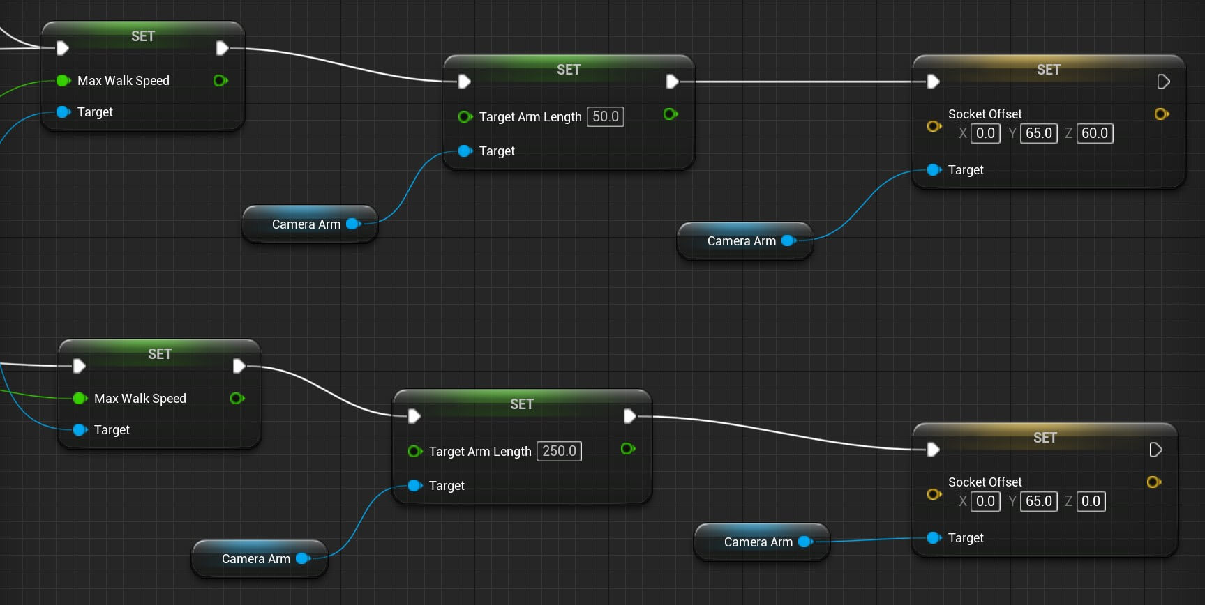
You can copy the nodes from here:
And this is how the aiming functionality looks like when we test the game:
The functionality we built in this part of the tutorial is slowing down the character when we aim and we explained how that happens above.
But you also see the aiming animation playing whenever we aim and it’s because of the Aiming Down Sights parameter which is set to true or false depending on if we are aiming or not. And depending on the true or false value we play the aiming animation.
Another thing is that the walk animation is being played while we are aiming which is the result of the blending nodes we used in the animation which we explained how they work when we created them a few steps back.
Drawing The Crosshair On The Screen
While or player can aim, we don’t see where he’s aiming because we don’t have a crosshair on the screen.
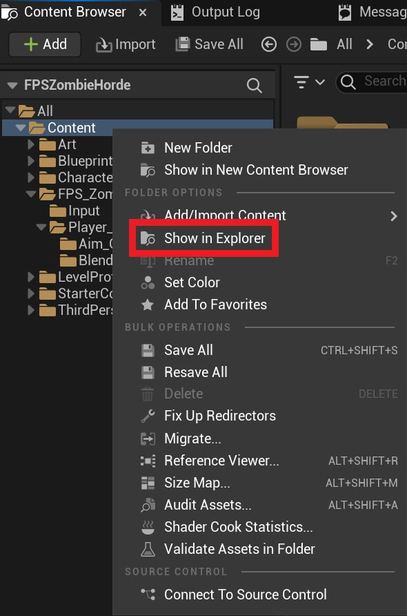
To add the crosshair, select the Content folder, then Right Click and Show In Expolorer:
Inside the zombie horde assets folder you’ll find a folder named Crosshair. Copy and paste that folder inside the Content folder that we just opened:
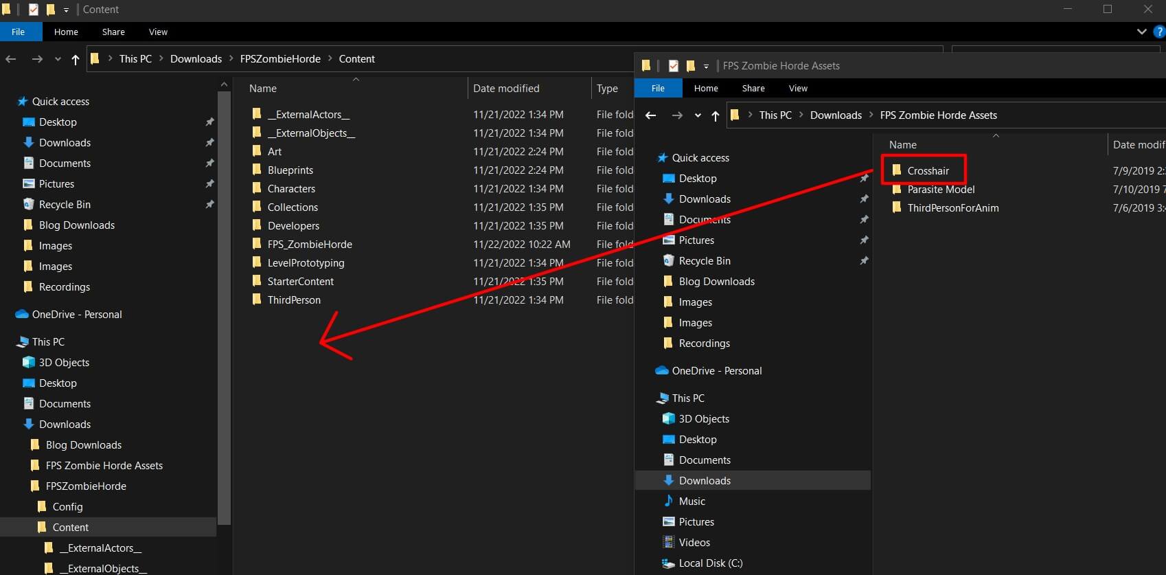
When you do that, you’ll see the Crosshair folder inside the Content folder in Unreal Engine:

Inside the FPS_ZombieHorde folder create a new folder and name it HUD. Inside the HUD folder Right Click -> Blueprint Class and in the search filter for hud:
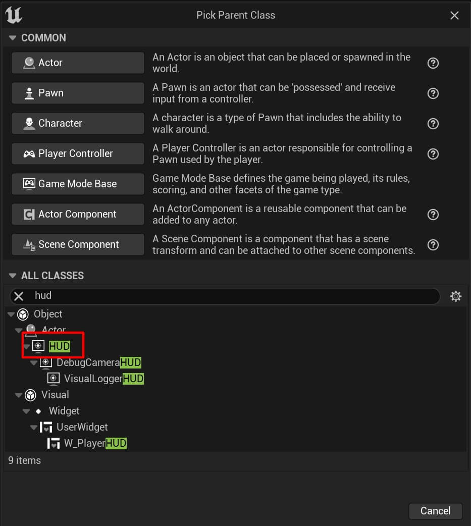
Select the HUD class and create a new bluprint, name it Crosshair_HUD and open it in the editor. Inside the event graph for the Crosshair_HUD add the following nodes:
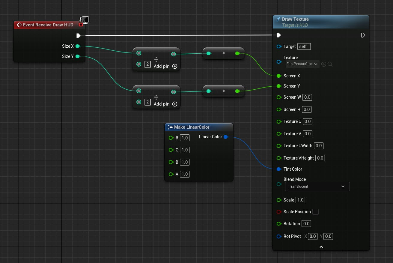
The Draw Hud node is going to draw the hud and it has the X and Y coordinates of the screen. Because we want to draw the crosshair in the center of the screen we’re diving X and Y by 2 which is going to give us the center of the screen coordinate.
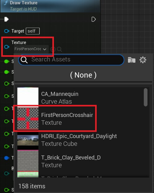
To draw the crosshair we use the Draw Texture node and we pass the texture we want to draw, X and Y coordinates, and the tint color.
For the texture parameter make sure that you select the crosshair image we imported:
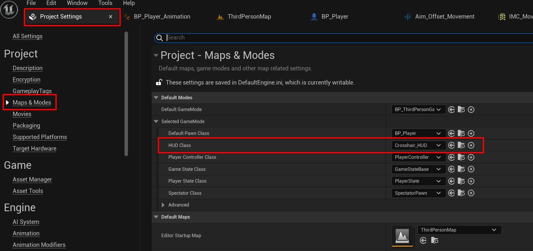
To draw the HUD on the screen, we need to go to Project Settings -> Maps & Modes and for the HUD class select the Crosshair_HUD:
If we run the game now, we’ll not see the hud on the screen. And the reason why is because we didn’t set the width and the height of the hud inside the Draw Texture node.
If you hover over the FirstPersonCrosshair asset we imported you’ll notice that its dimensions are 16×16:
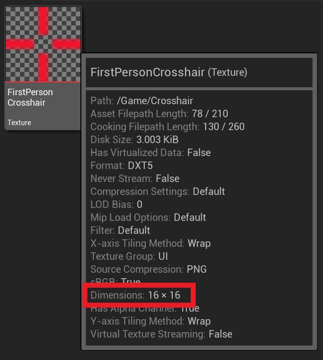
This means we need to specify these values in the Draw Texture node:
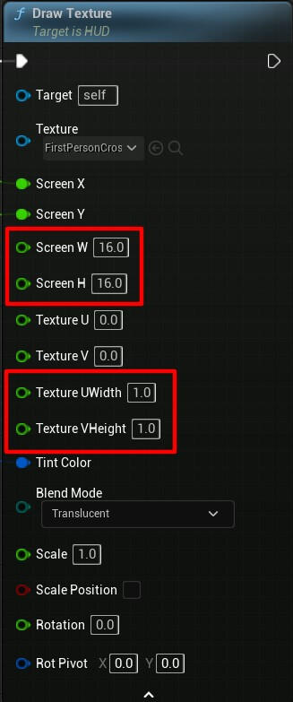
Screen W and Screen H represent the width and the height of the texture on the screen where it will be drawn. And the Texture UWidth and Texture VHeight are the scale that’s why we set the value to 1 meaning it will have a full width and height.
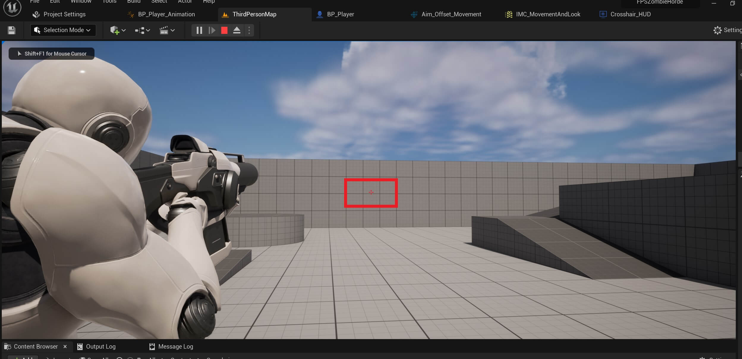
When we run the game now, we’ll see the crosshair drawn in the middle of the screen:
Player Shooting Functionality
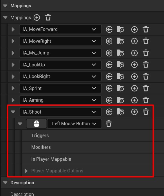
To create the shooting we first need to create an input action. So create a new input action, name it IA_Shoot, add it in the IMC_MovementAndLook and set it to trigger when the Left Mouse Button is pressed:
Since the shooting functionality is a little long, I’ll add it piece by piece and explain every step along the way.
We’ll start with the IA_Shoot input action:
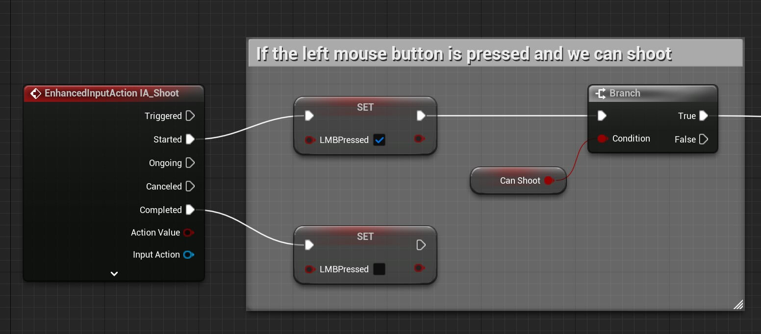
When we press the Left Mouse button the IA_Shoot will be triggered, specifically the Started event.
When that happens we’ll set the LMBPressed to true, and then we’ll enter a branch where we’ll test if Can Shoot is true. If it’s true, then we’ll move forward to perform the shoot.
When we release the Left Mouse button the Completed event of the IA_Shoot input action will be triggered. And for that, we’ll just set the LMBPresset to false.
Next, we’re going to test the following condition:
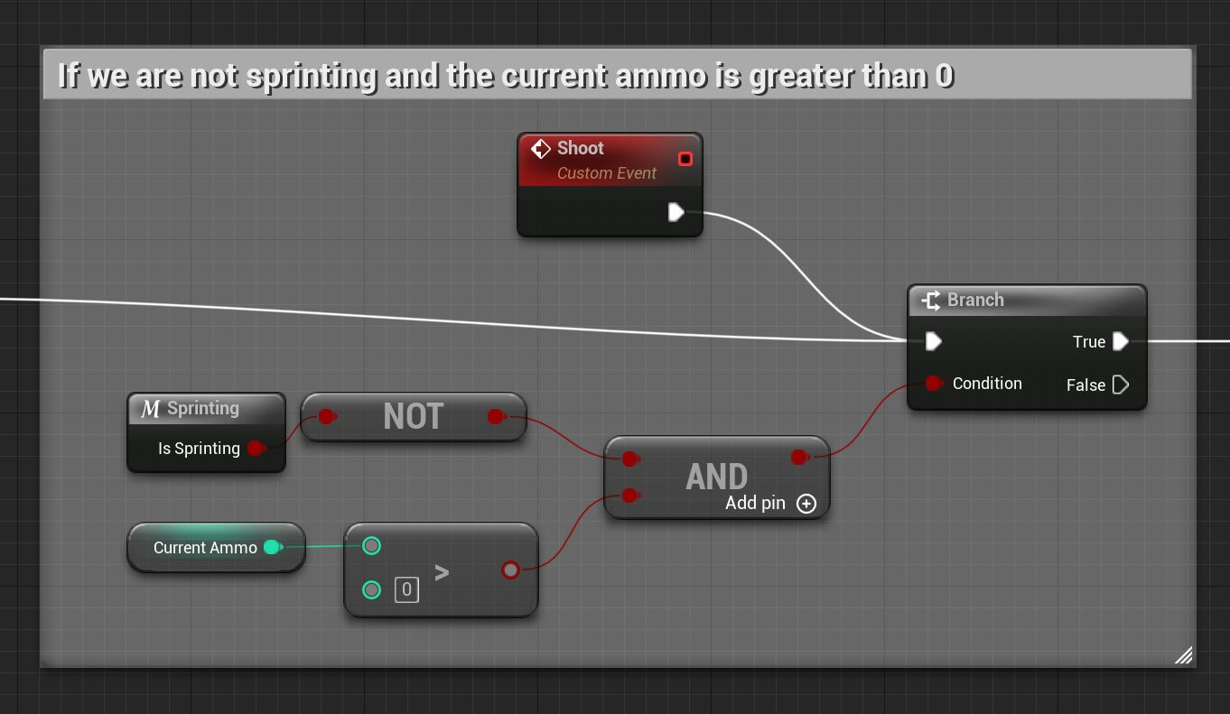
If we can shoot, we’ll enter a branch. The condition for that branch is if we are NOT sprinting and if the Current Ammo is greater than 0, meaning we have bullets to shoot.
Both of these booleans need to true, which is denoted with the AND node, so that the branch condition will be true.
We’ve also created a custom event and named it Shoot because we’ll call it at the end of the shooting functionality if the Left Mouse button is still pressed after we can shoot again.
Moving forward if the previous condition is true then:
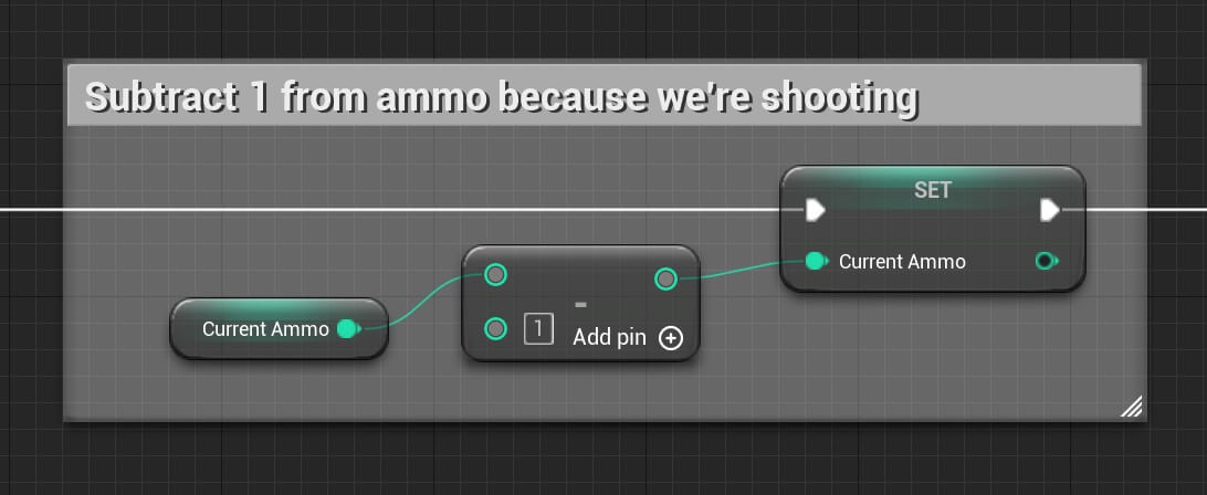
When we shoot we need to subtract from the Current Ammo value because every time we shoot one bullet we’ll have one bullet less.
Whenever we shoot, we are going to create a muzzle. To do that we add the following nodes:
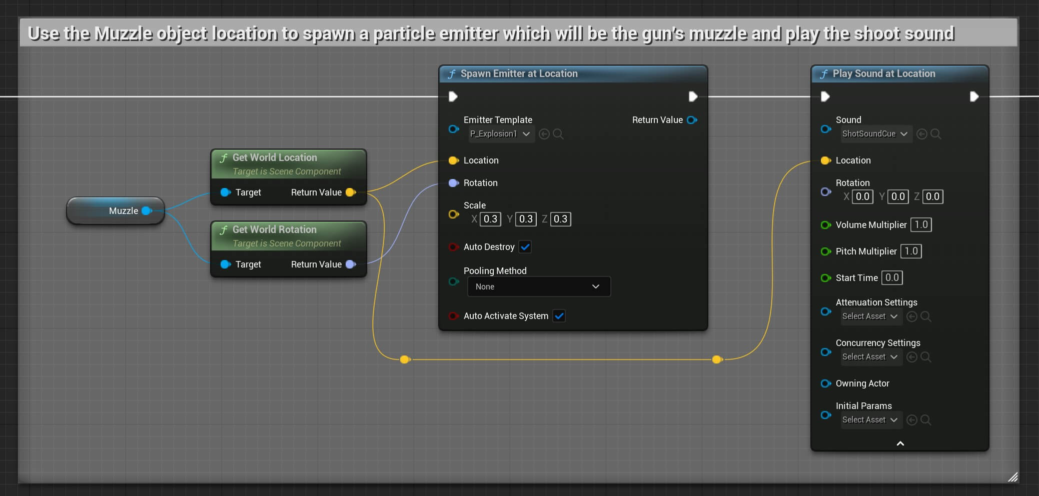
We’re using the Muzzle actor we created a few steps ago. The Muzzle actor is located right in front of the gun, or to be more precize where the bullet exits.
We use the Spawn Emitter at Location node to create an emitter e.g. a particle effect at the location of the Muzzle actor and using it’s rotation.
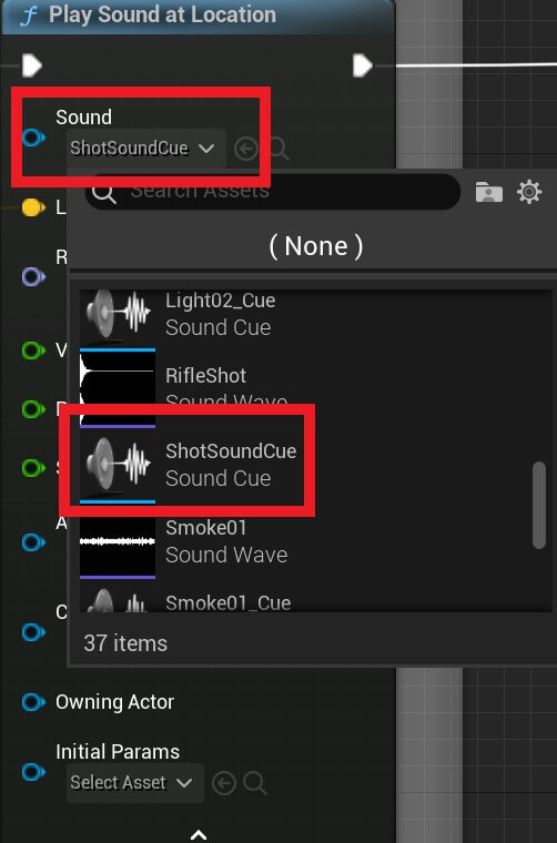
We also play the shoot sound effect at the location of the Muzzle actor by using the Play Sound at Location node.
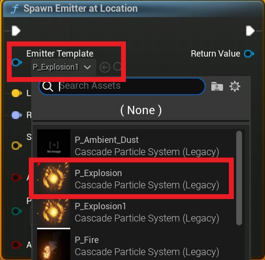
For the Emitter Template we use the P_Explosion1 which comes with the Starter Content which we checked at the beginning when we created the project.
You can simply filter for it in the Emitter Template drop-down list:
And for the sound, we’re going to use ShotSoundCue which you can filter in the search for the Sound in the Play Sound at Location node:
One cool effect that we’ll implement is camera shake when we shoot, which will make the shooting look more realistic. And we’re going to do that with the following nodes:
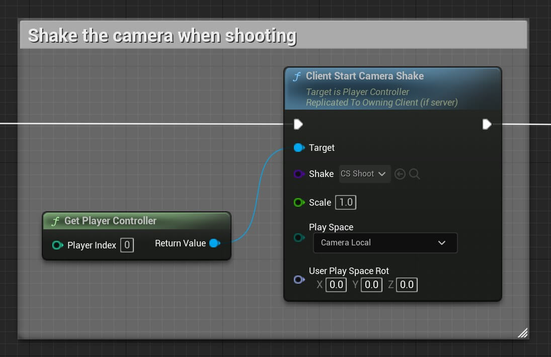
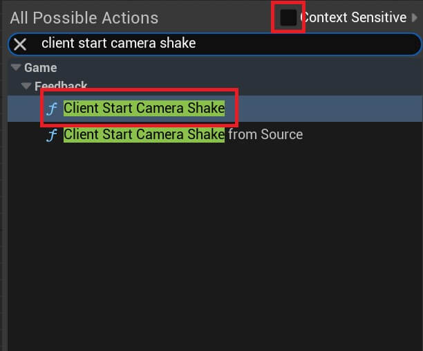
If you can’t find the Client Start Camera Shake node, uncheck the Context Sensitive in the search node:
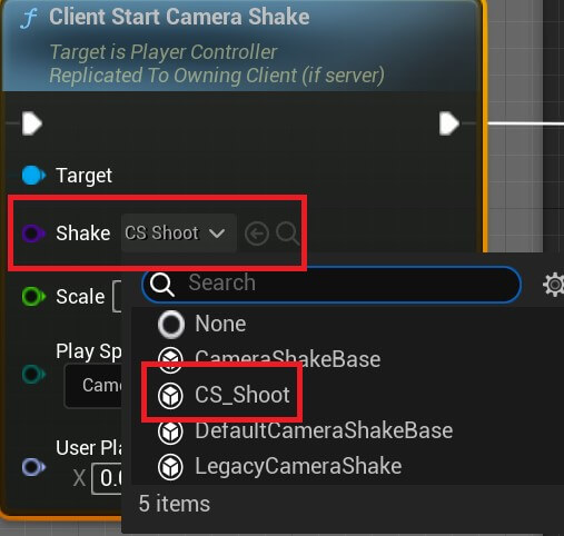
For the shake effect we’ll use CS Shoot, which you can find in the drop-down list for the Shake option:
To simulate a bullet hit, we’re going to use raycasting with the following nodes:
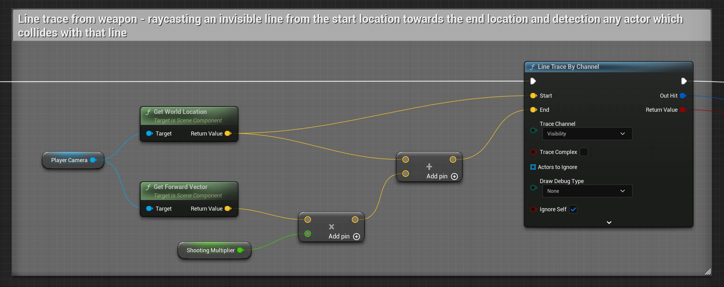
Raycasting means we’re drawing an invisible line in the direction we specify and if anything collides with that line we can detect it.
Line Trace By Channel will draw the invisible line using the Start parameter as the starting position of the line, and using the End parameter as the end position.
For the starting position we’re using the Player Camera’s location, which is basically the camera under the Camera Arm component for the player:
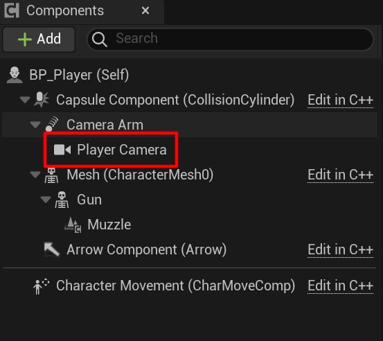
I renamed the camera so that it’s easier to understand which components we’re using.
So the starting position is the player’s camera location, the end position is the forward vector of the player’s camera multiplied with the Shooting Multiplier variable which we created because we needed to multiply the forward vector so that the line is drawn from the player’s camera location in the forward direction.
This is the value of the Shooting Multiplier variable:

This means that the line drawn will be as long as the value of the Shooting Multiplier variable.
After we draw the line, we’re going to do the following:
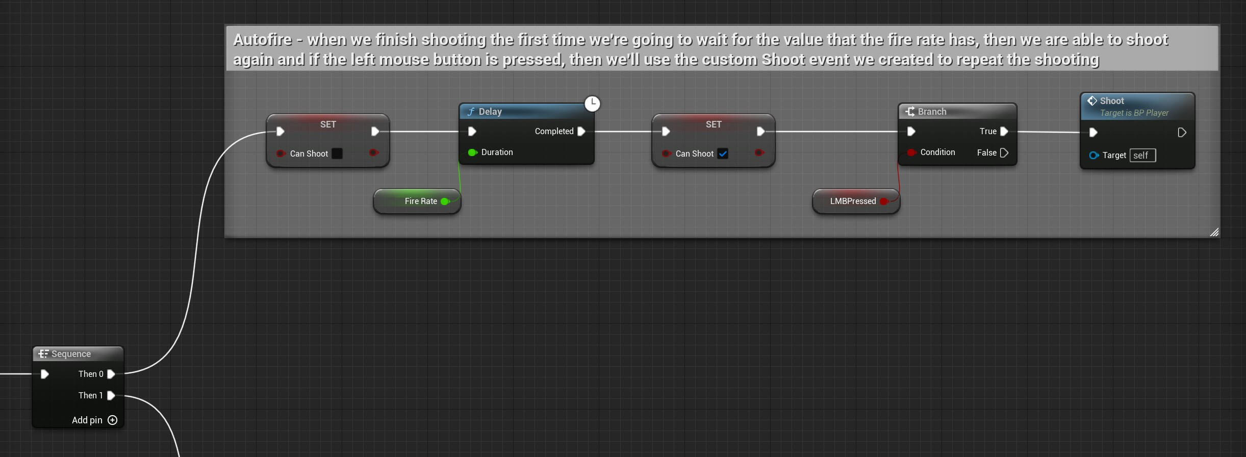
We are going to enter a sequence and in the sequence we can specify operations that will be executed in the order in which we place them.
The first operation in this sequence is going to disable the player from shooting by setting the Can Shoot to false.
This will make the player shoot in time intervals instead of making him shoot hundreds of times in a second if we didn’t control the shoot rate.
For that we’re using the Fire Rate variable and we are going to wait using the Delay function. When the wait is over we are going to set Can Shoot back to true, and we are going to test if the Left Mouse Button is pressed, if that is true we are going to call the Shoot custom even which we created here:

By calling the Shoot event we are skipping the first grop of testing which is setting the LMBPressed variable to true – meaning we are pressing the Left Mouse button so the shooting continues.
And finally, the last thing we’ll do is create an explosion effect where the line trace hits with the following nodes:
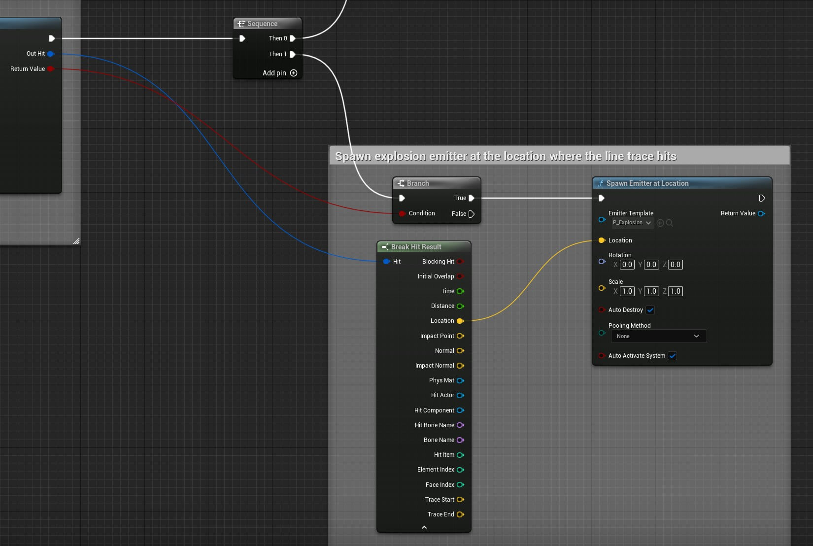
In the second operation first we’ll test if the Return Value of the Line Trace By Channel is true, if that is the case it means the line has hit an actor.
When that happens we are going to use Spawn Emitter at Location node to spawn the P_Explosion particle which you can select from the Emitter Template the same way we did for the muzzle effect a few steps back.
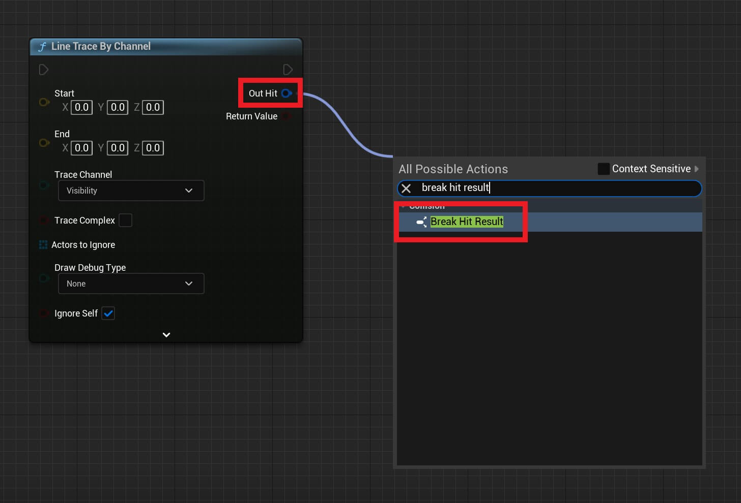
The location where we will spawn that emitter is the location of the hit result. And you can access that location by draging a node from the Out Hit parameter and selecting Break Hit Result:
You can copy the full node structure from here:
So now, let’s the test the shooting functionality:
The shooting works, and we spawn the explosion particles where the line trace hits.
But we do have one issue and that is the bullet that we shoot or the explosion effect is not spawn in the middle of the crosshair, and you can see that at the end of the above video.
The issue here is because of the crosshair asset, which has the 16×16 dimensions which we already shown:

Because of the 16×16 dimensions, we need to add two more nodes in the calculation of the position where the crosshair will be drawn inside the Crosshair_HUD:
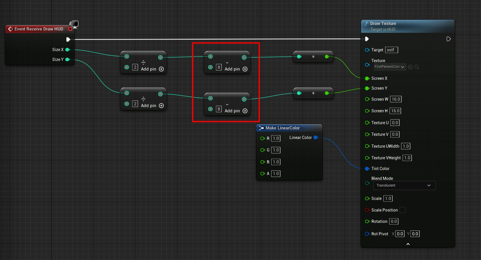
So when we calculate the center of the screen by dividing Size X and Size Y by 2, we are also subtracting 8 from both which totals 16 and that was the missing piece of the puzzle which will draw the crosshair exactly in the center of the screen.
So when we test the shooting now, this is how it looks like:
Reloading The Gun
While the shooting works we have a limited amount of bullets – 30 to be precise which is the default value of the MaxAmmo and CurrentAmmo variables.
So when we shoot 30 times we are not able to shoot again until we close the game and play it from start. To fix that we are going to implement the reloading functionality.
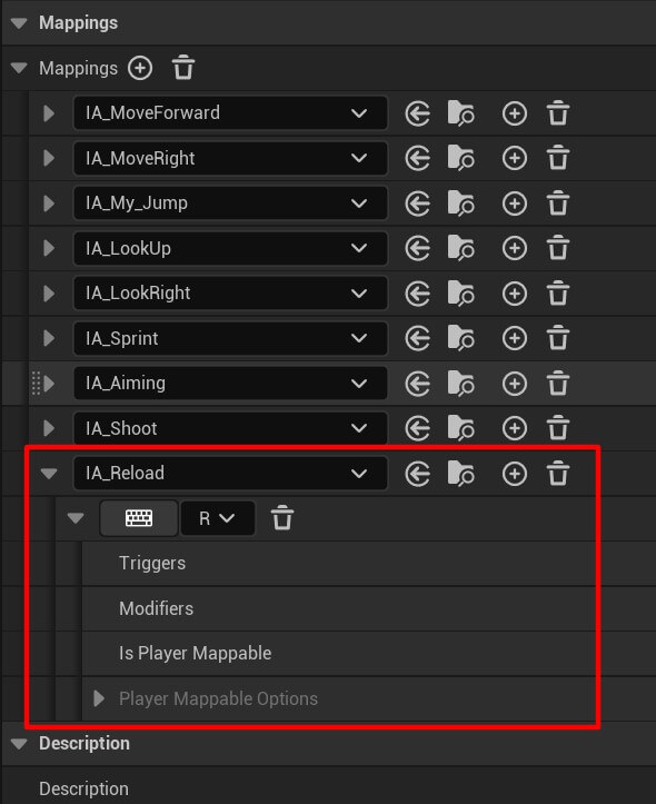
Create a new Input Action, name it IA_Reload and add it in the IMC_MovementAndLook:
When we press the reload button, first we’ll check if we are already playing the reload animation:
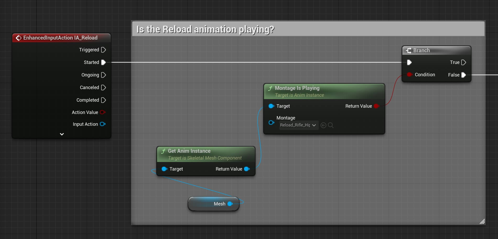
The mesh is the mesh component of the player character where the BP_Player_Animation is attached:
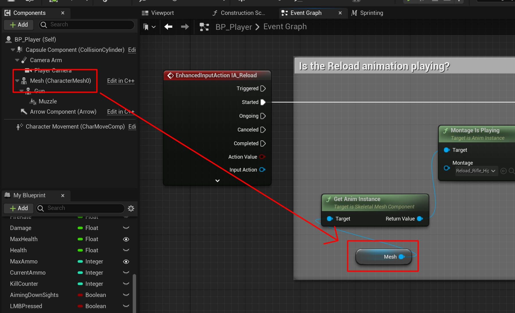
The reload animation is called Reload_Rifle_Hip_Montage and you can search it from the drop-down list of the Montage Is Playing Node:
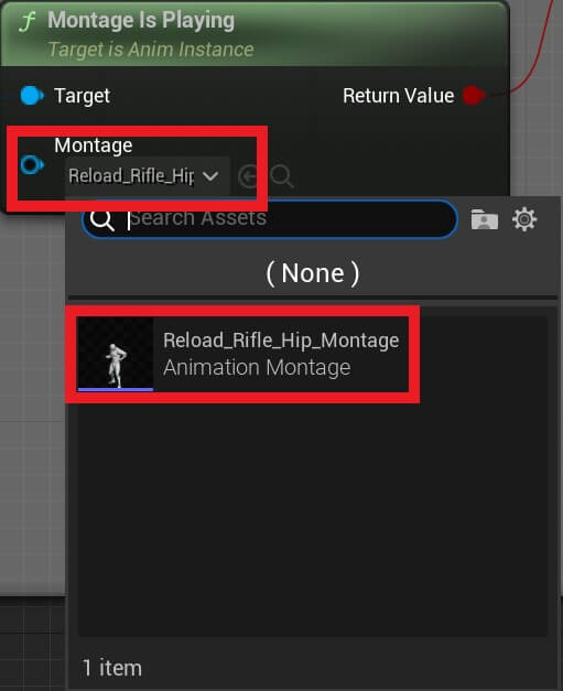
The reason why we are testing if we are currently playing the reload animation is because if we are playing the animation then we’ll wait for it to end and not play the same animation twice at the same time.
So if we are not playing the reload animation we’ll do the following:
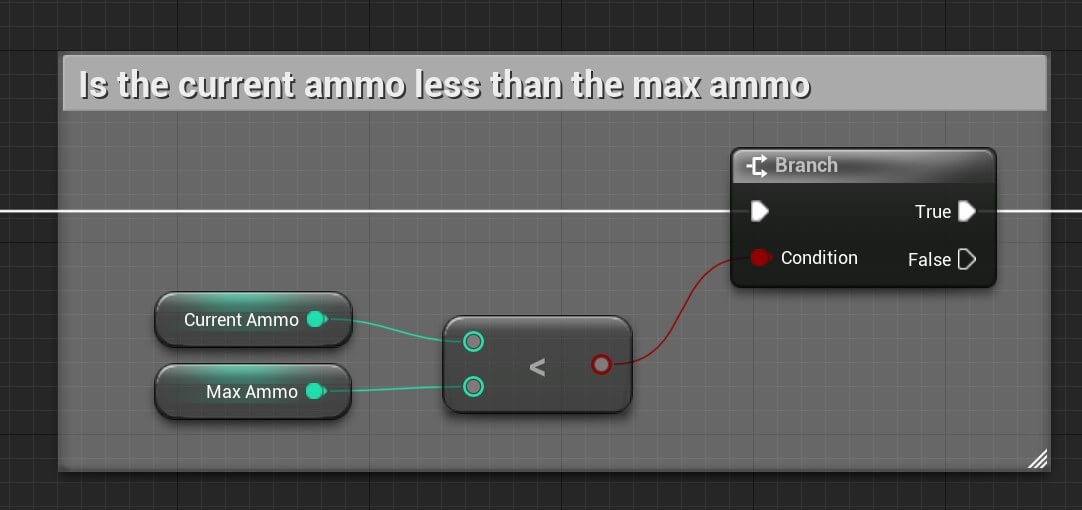
We are testing if the current ammo is less than the max ammo. Because if the current ammo is the same as max ammo then there’s no need to reload the gun because we are already at the full ammo capacity.
But if the current ammo is less than the max ammo then:
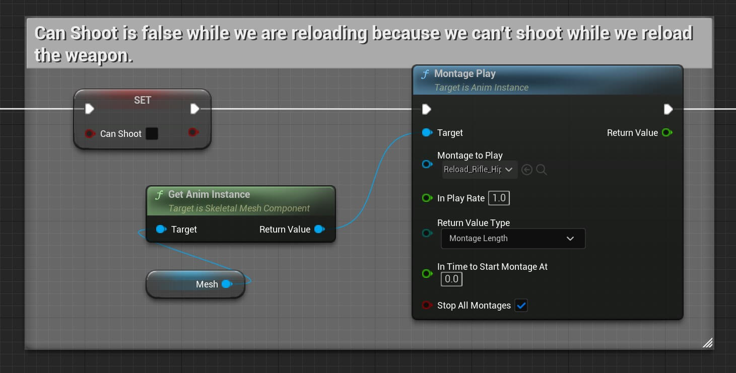
First we’ll set the Can Shoot to false because we don’t want to allow the player to shoot while we are reloading.
Next we’ll play the reload animation with the Montage Play node and in the Montage To Play drop-down list select the same Reload_Rifle_Hip_Montage.
After that we go in a sequence:
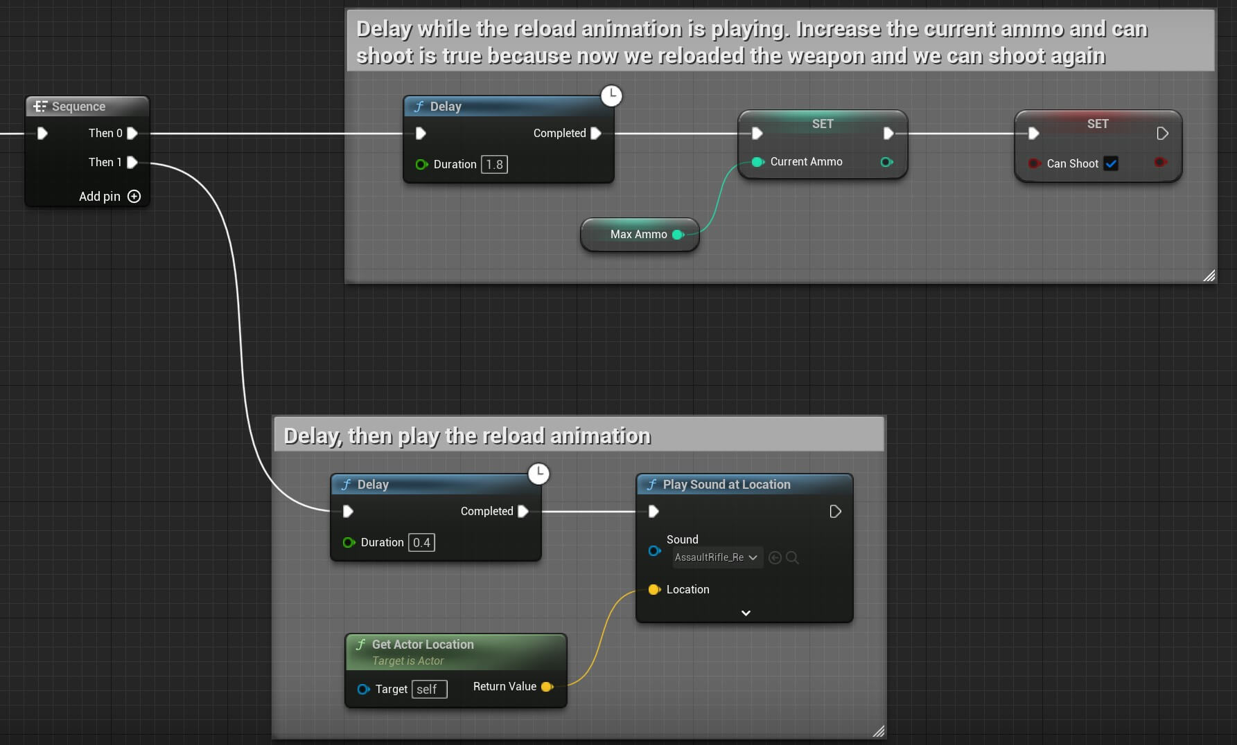
In the first sequence execution we use the Delay node to delay 1.8 seconds while the reload animation is playing. Then we set the Current Ammo to be equal as the Max Ammo and finally we set allow the play to shoot again with the Can Shoot variable.
In the second sequence execution we delay 0.4 seconds and we play the reload sound at the player actor’s location using the Play Sound at Location node and passing the AssaultRifle_Reload sound.
You can copy the whole node structure from here:
We can run the game and test the reload animation and functionality:
Animating The 3D Parasite Model
The parasite model we’ll use in this game is downloaded from www.mixamo.com:
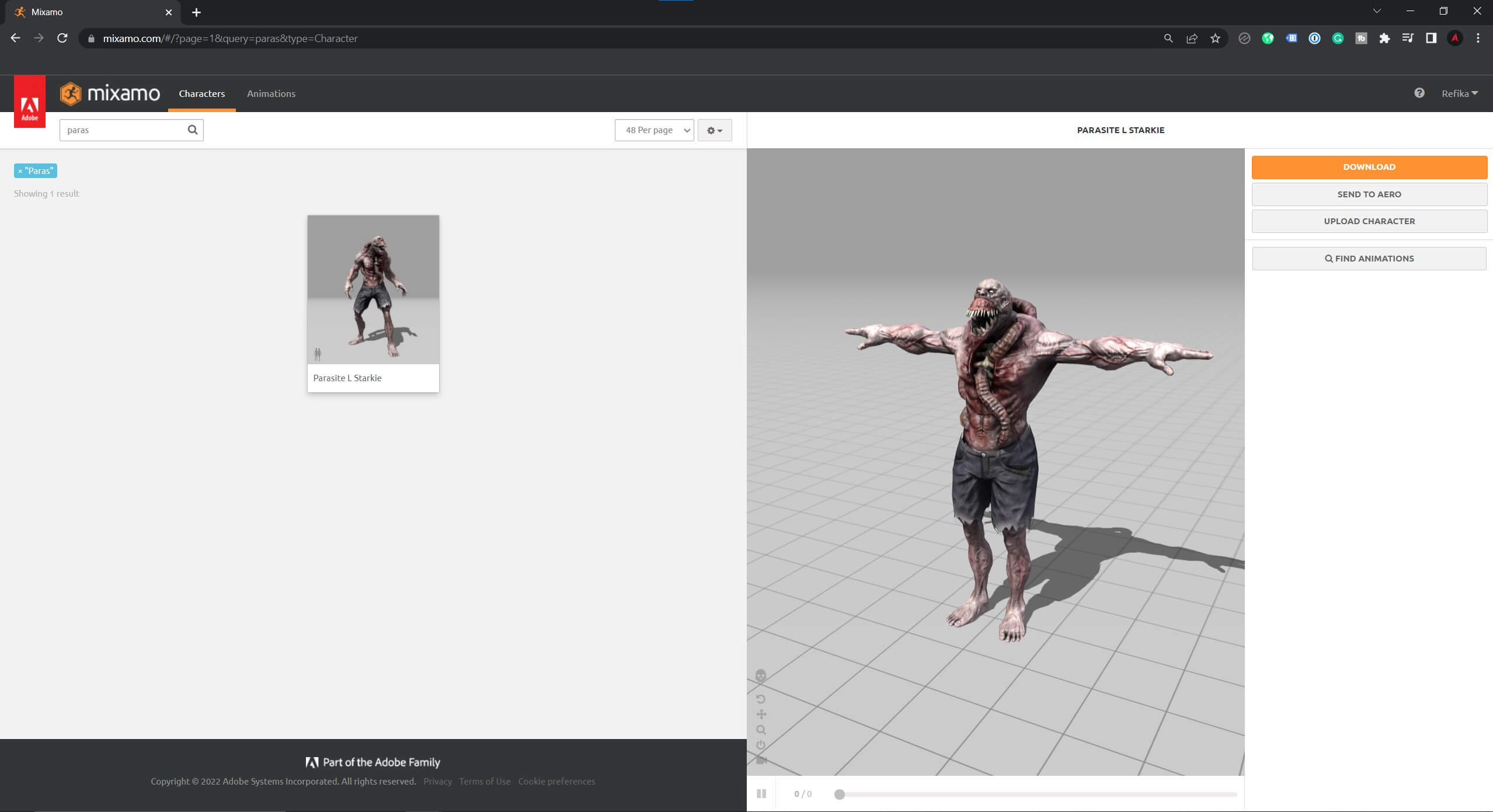
Mixamo is a really useful site for game developer becuase all the 3D models are free, plus you can animate them and you can even upload your own 3D models, rig them, and animate them.
We’ll not go into the details how to do all that, we’ll create a separate post, if we didn’t do that already, where we’ll demonstrate in detail how to use the mixamo website to get 3D models for your game.
As for the parasite model you can find it in the assets folder which you downloaded for this tutorial.
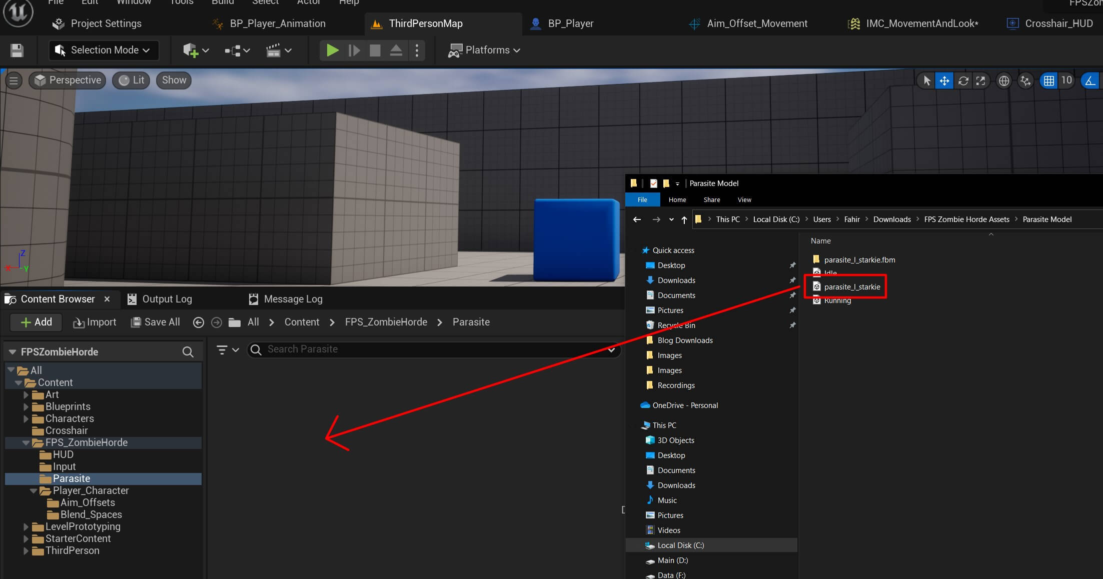
Inside the FPS_ZombieHorde create a new folder and name it Parasite. In the assets folder find the Parasite Model folder and drag the following file in the Parasite folder in Unreal Engine:
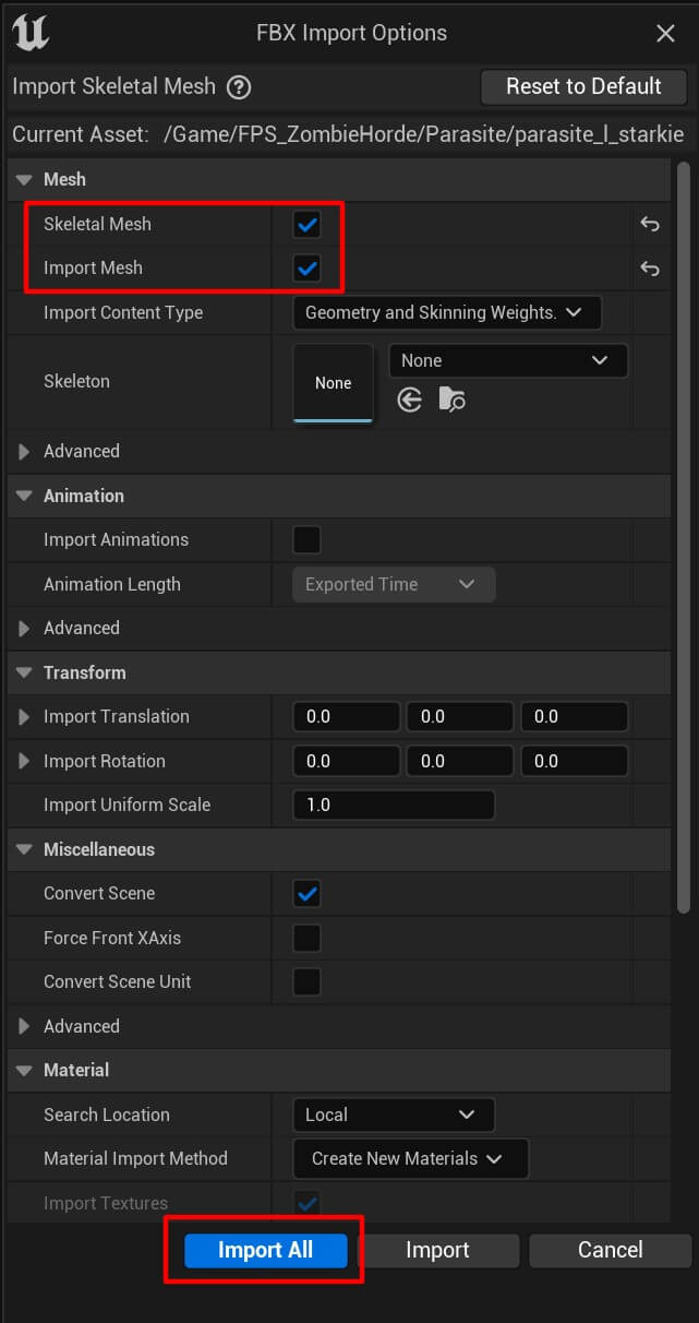
In the next window make sure that the following options are checked and then click Import All button:
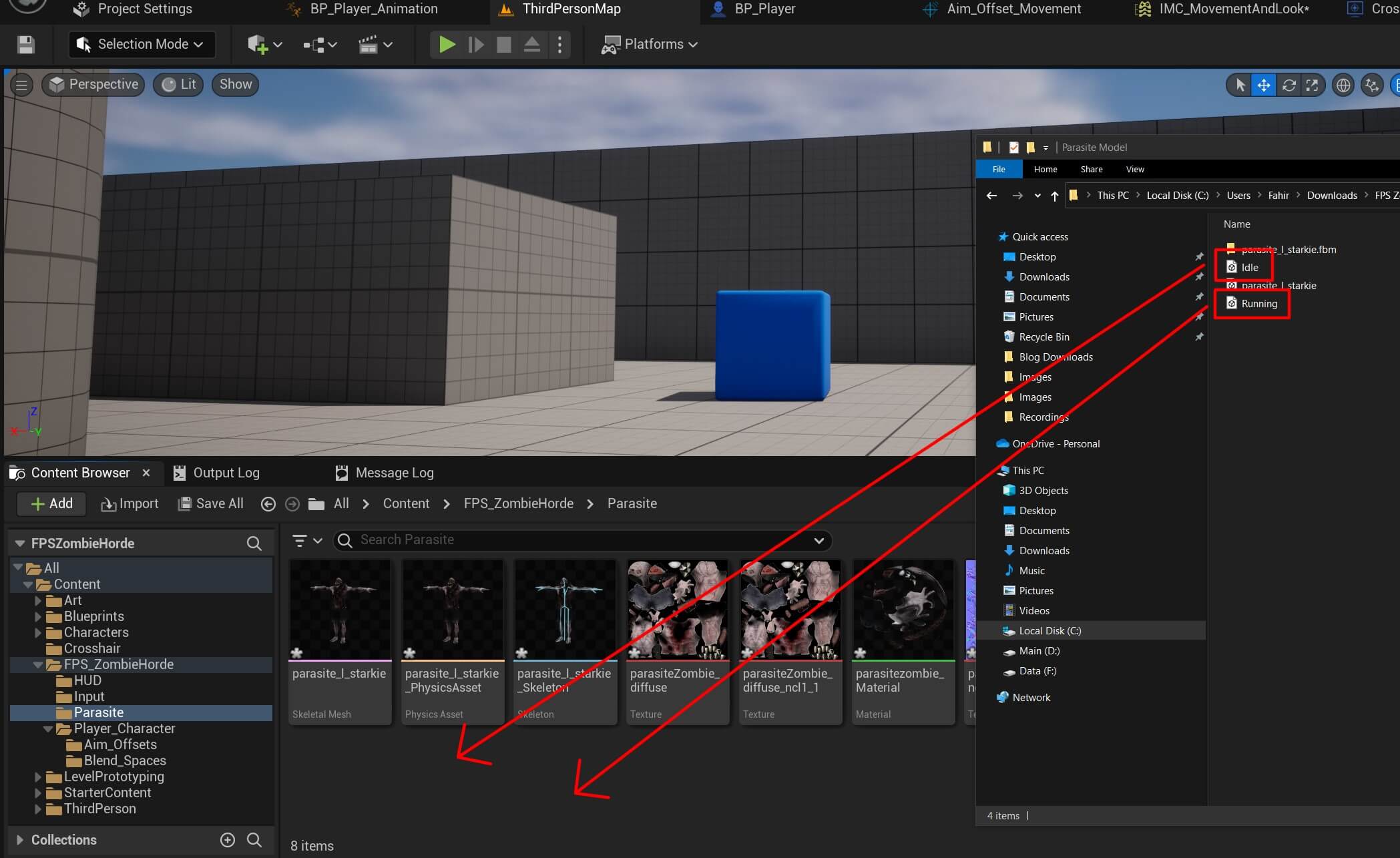
Now that we imported the 3D model we can import his animations by dragging them in the same folder:
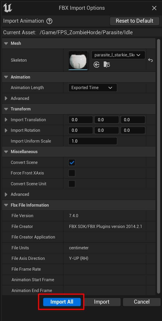
In the next window click the Import All button:
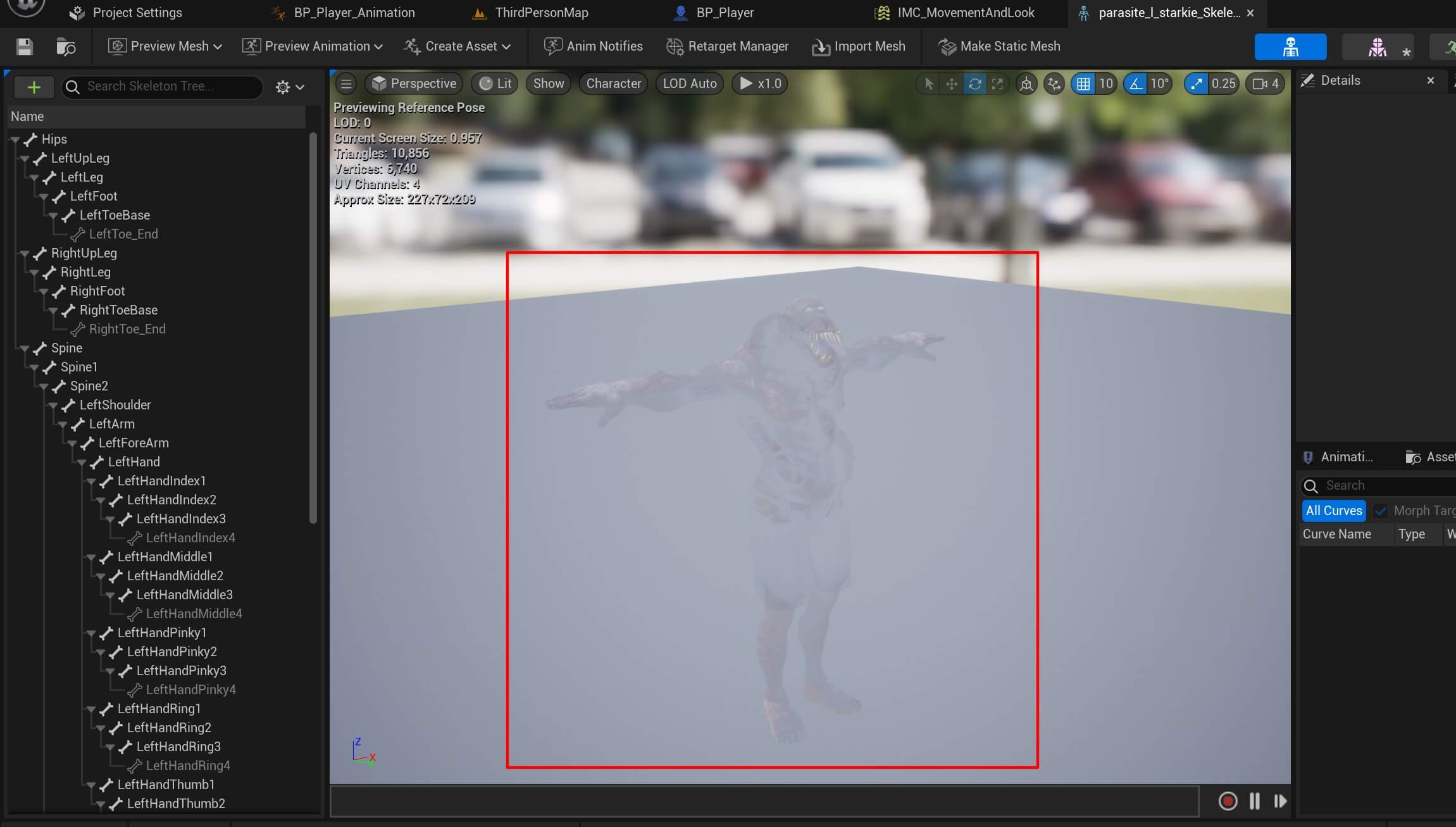
Before we animate the parasite we need to fix one problem. If you open the skeleton of the model:

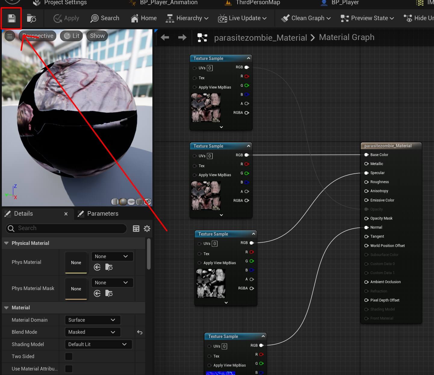
You’ll notice that the parasite model is transparent:
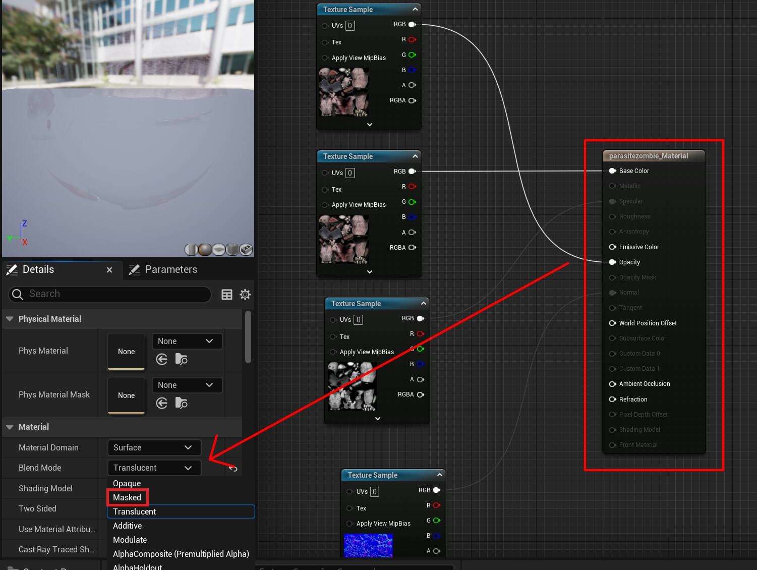
To fix this issue, we need to open the material of the parasite model:

Inside the material editor we need to select the parasitezombie_Material and in the Material tab change the Blend Mode option from Translucent to Masked:
When you do that, press the Save button at the top left corner:
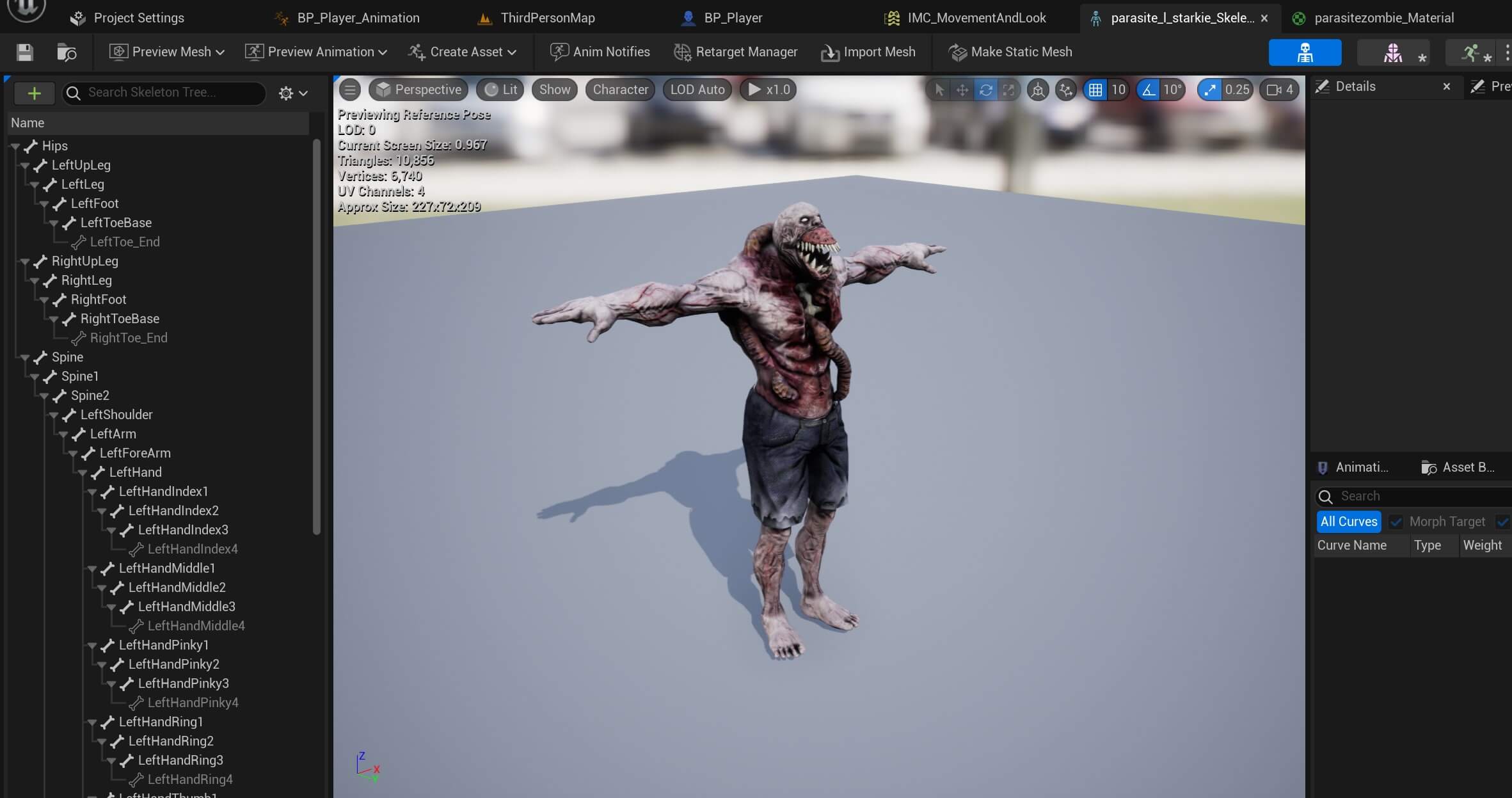
Now when we open the skeleton of the parasite model again we’ll see that the 3D model is not transparent anymore:
Moving forward we are going to create the parasite blueprint and it’s animation.
Inside the FPS_ZombieHorde folder create a new folder, name it Parasite_Blueprints and create a new blueprint class which inherits from the character class:

Name the blueprint BP_Parasite open it in the editor and do the following:
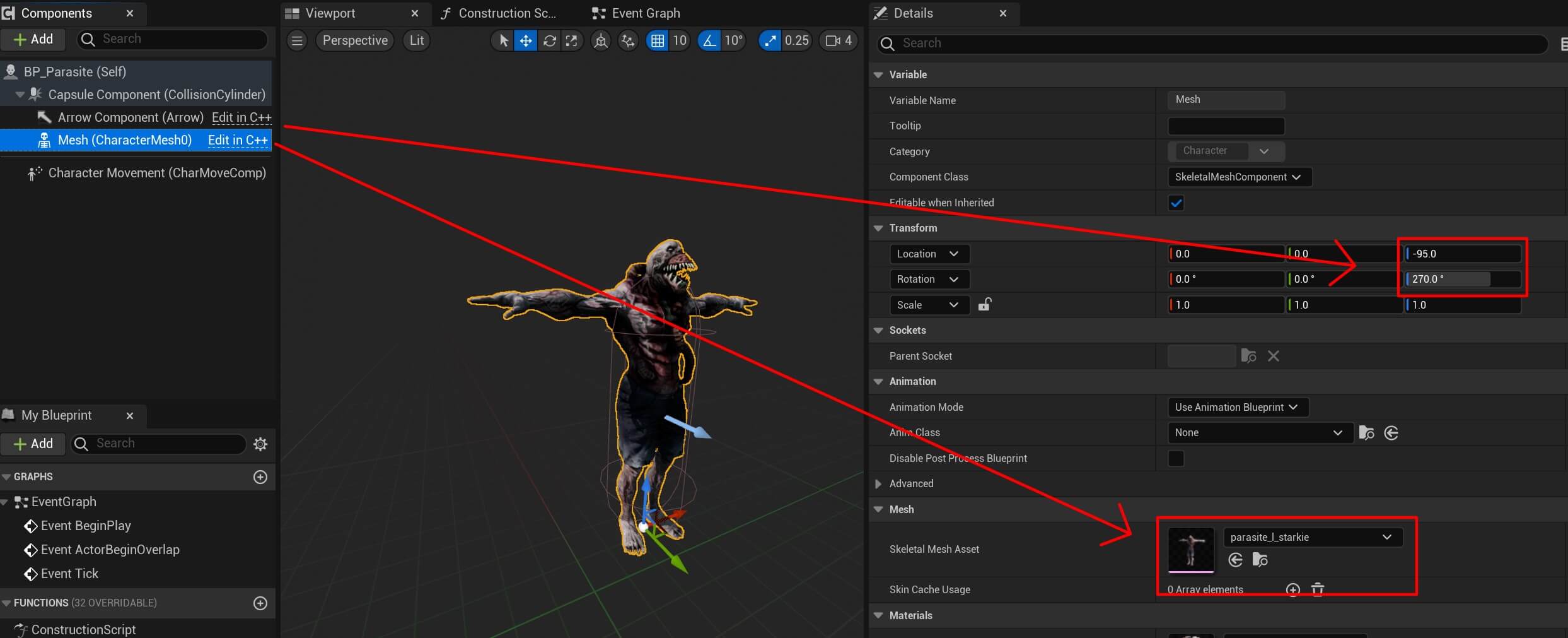
For the mesh model select the parasite we imported. Inside the Transform component for the Z axis set the value to -95 and for the Z rotation set the value 270.
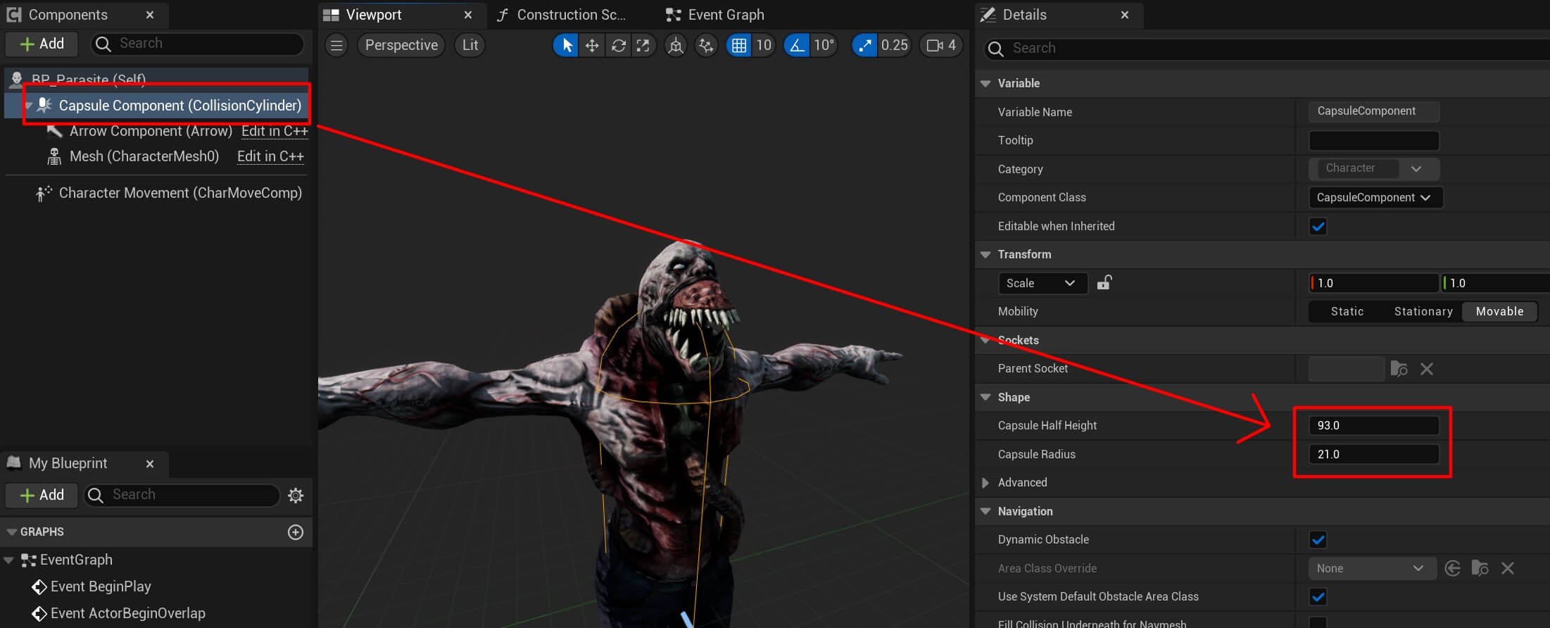
Next, select the Capsule component and for the height set the value to 93 and for the radius set the value 21:
Now inside the Parasite_Blueprints folder create a new animation blueprint:

For the skeleton select the parasite model skeleton:
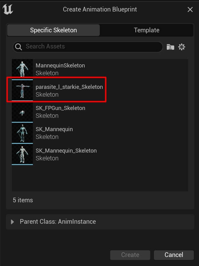
Give the new blueprint name BP_Parasite_Animation and then create a new blend state:

Select the parasite skeleton:
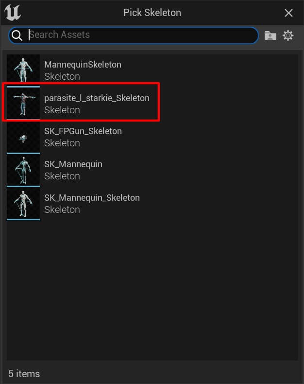
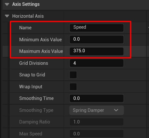
Name the blend space Idle_Run_Enemy and open it in the editor. In the axis settings set the following values for the horizontal axis:
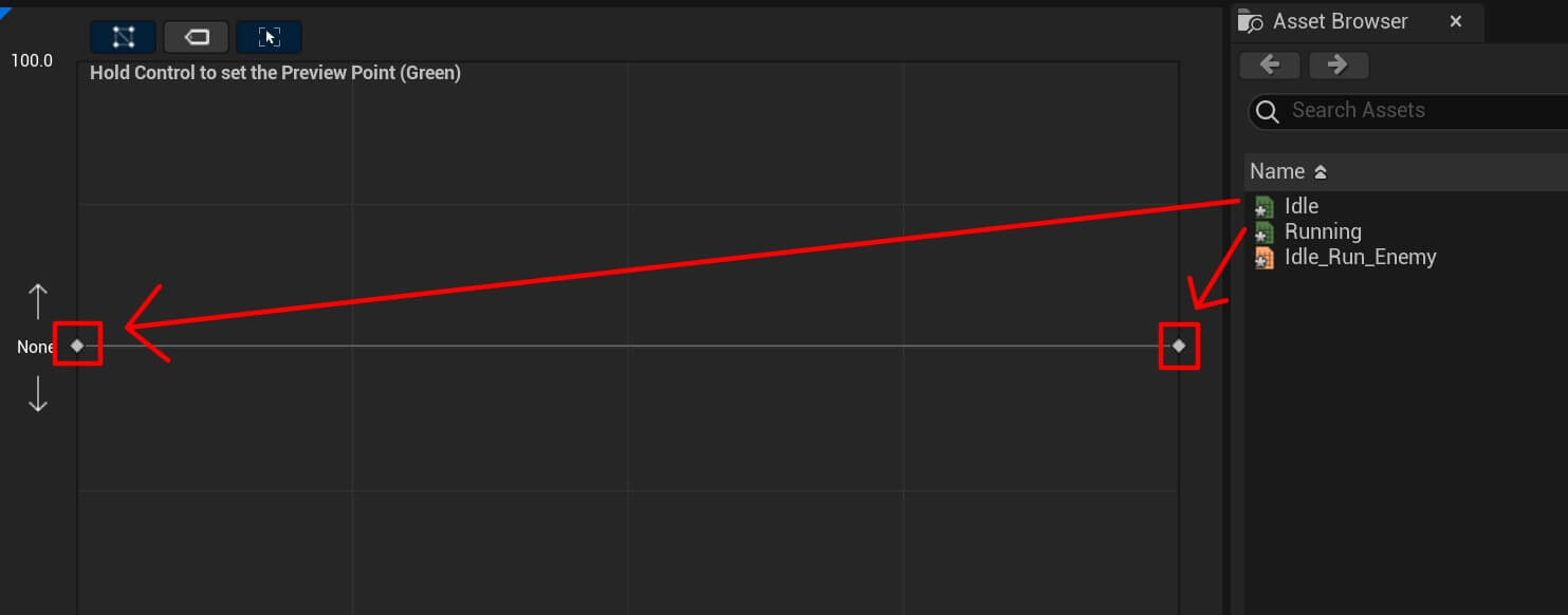
From the Asset Browser drag the Idle and Running animation in the following places:
Inside the BP_Parasite_Animation create a new state machine:

Name it Default and inside create a new state:

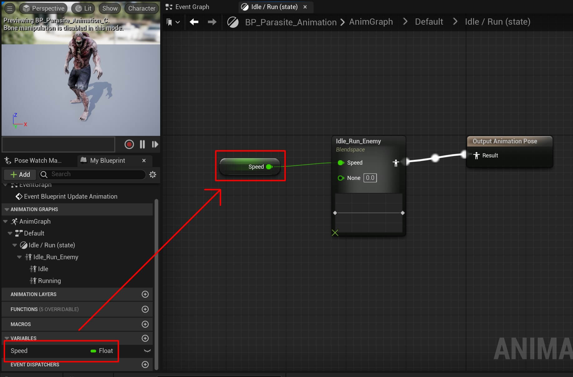
Name the state Idle / Run. Create a new float variable, name it Speed and plug it in the Idle_Run_Enemy blend space:
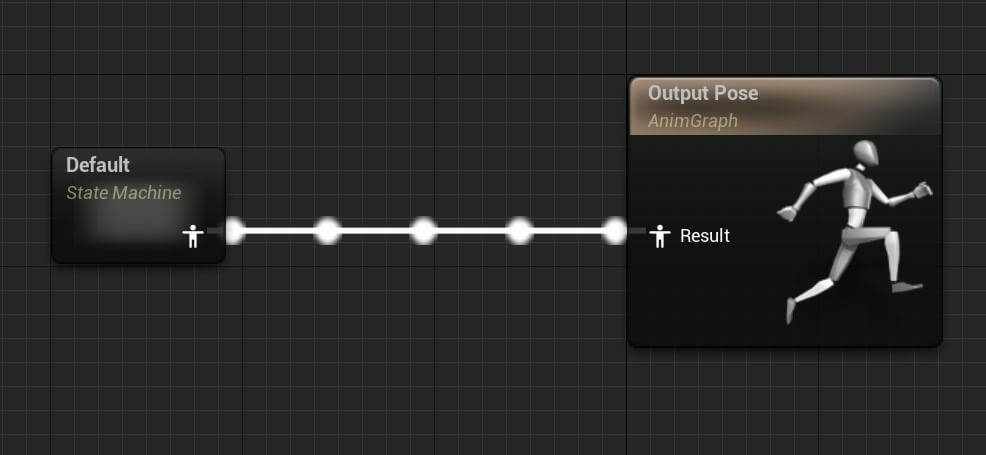
Also make sure that the Default state machine is plugged in the output pose:
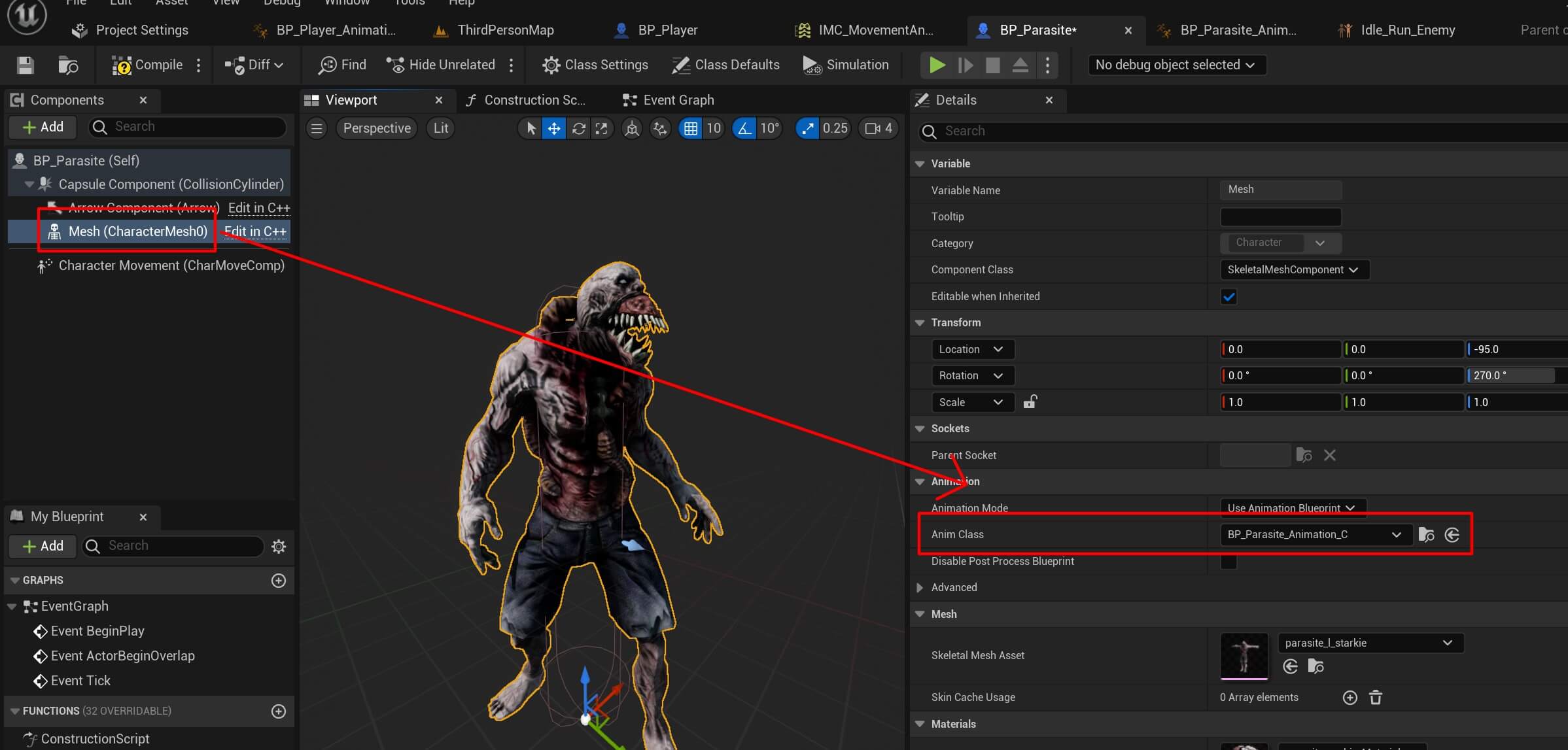
And lastly, set the BP_Parasite_Animation as the animation blueprint for the parasite mesh inside the BP_Parasite:
Creating The Enemy AI System
To create the enemy AI system first we are going to create the variables we’ll need for that inside the BP_Parasite:
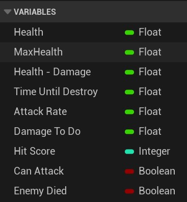
We are also going to set the initial values for the following variables:


Other variables are going to have default values. Next, inside the Event Graph we are going to create the enemy AI behavior starting with:
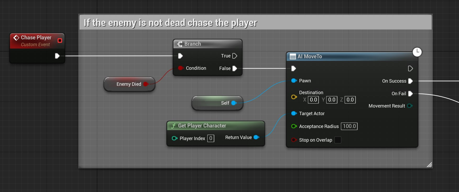
We created a custom event and named it Chase Player. When we call that custom event first we’ll test if the enemy has died, if that’s false then we’ll call the AI Move To node which takes a pawn – the pawn which will be moved, in this case it’s the parasite and that’s why we got a reference to self because the variable self referst to the BP_Parasite.
The Target Actor parameter is the target to which AI is going to move, in our case the player character.
And the Acceptance Radius which is set to 100 is the radius range where the AI is going to stop e.g. when the AI gets 100 units close to the Target Actor it will stop moving.
So when we reach the player character we are going to attack him:
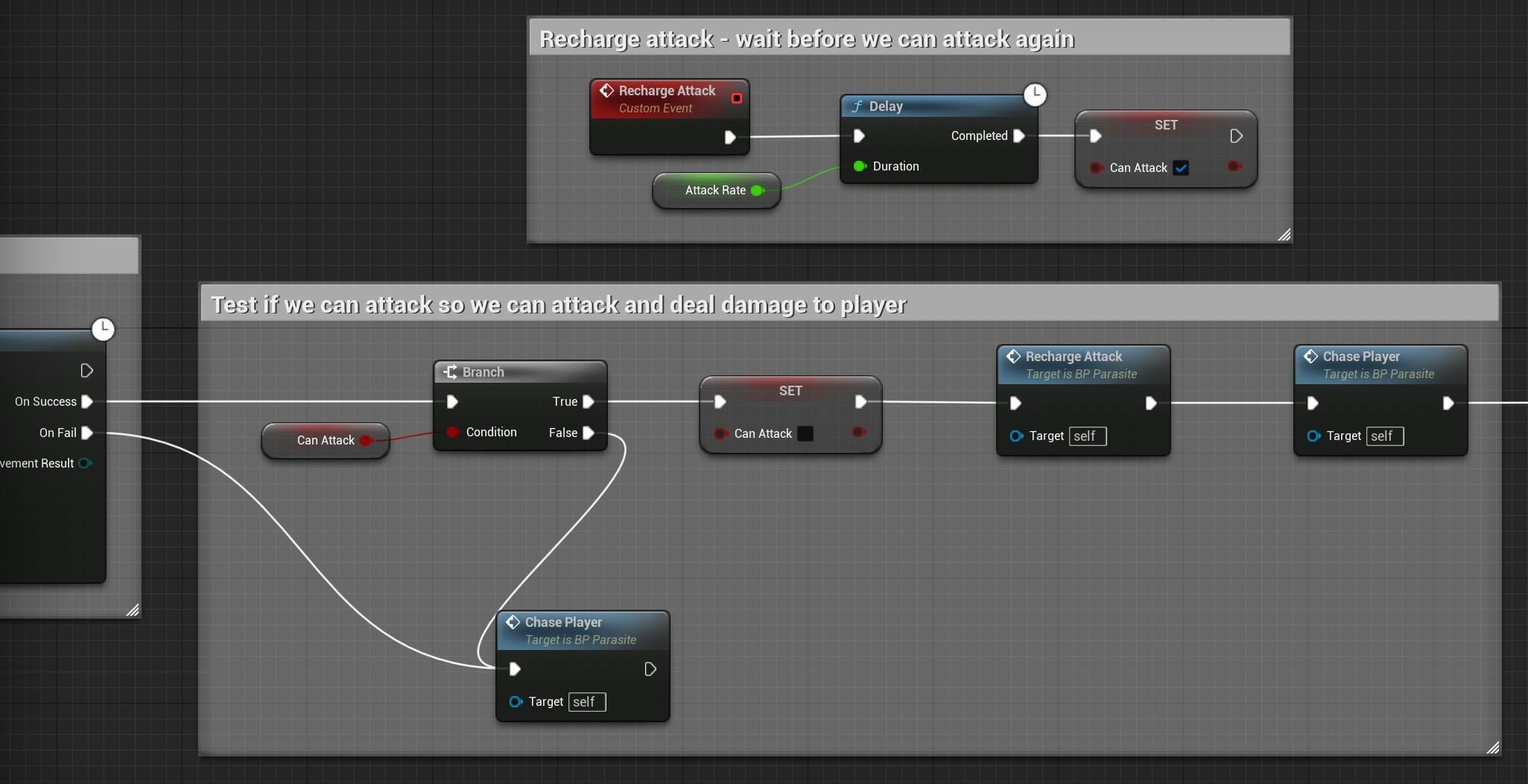
First you’ll notice that the attack will happen only for the On Success event of the AI Move To, because only if we get to the player and the enemy is within his reach we’ll attack.
In case if the enemy fails to reach the player, then the On Fail event will be trigger and in that case we’re calling the Chase Player custom event to repeat the process and make the enemy chase the plaeyr again.
Inside the On Success first we’re testing if the enemy can attack because we don’t want to allow the enemy to perform hundreds attacks in a second.
If the enemy can’t attack we are calling Chase Player to make the enemy chase the player again.
But if the enemy can attack we set the Can Attack to false so that the enemy doesn’t perform multiple attacks, then we call Recharge Attack custom event which we created.
This event simply calls the Delay node and passes the Attack Rate which we use as the wait time before we allow the enemy to attack again. So when the wait is over we set the Can Attack to true.
After that we call the Chase Player custom event again to make the enemy chase the player and perform another attack.
And lastly we deal damage to the player:

For now, we’re using the Print String node to print on the screen when the enemy deals damage to player because we didn’t create that funcionality in the BP_Player blueprint.
The last step is to initialize this behavior when the enemy actor is created in the game:

You can copy the nodes from here:
To test this out, drag the BP_Parasite inside the map:
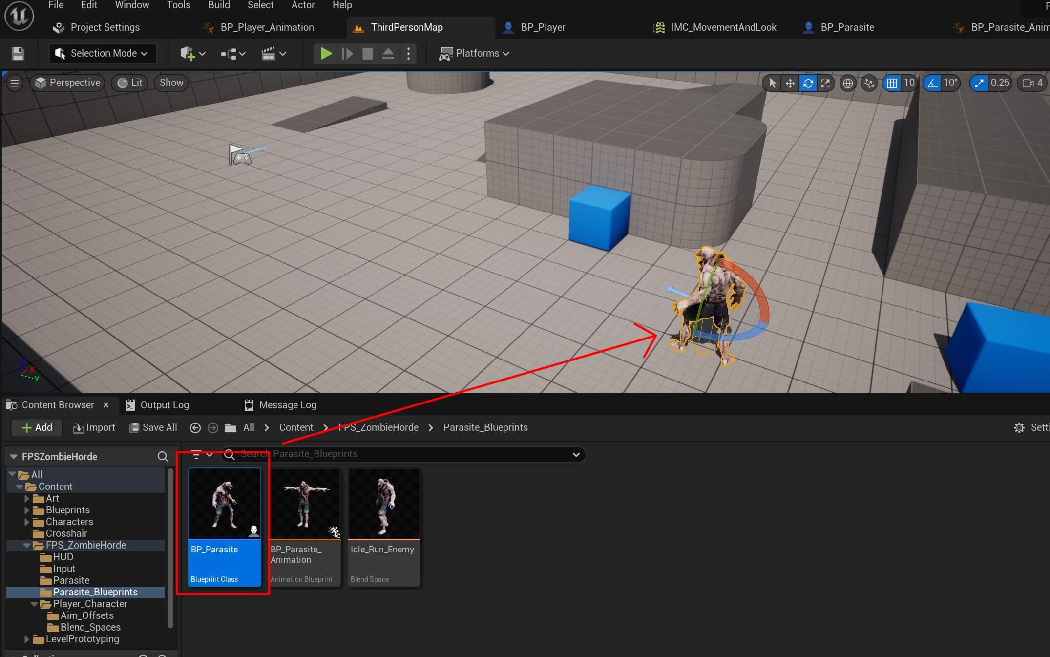
When we run the game now, this happens:
The enemy was just standing still. And the reason why is because we need to do one more thing to make the AI work.
But before we do that, we’ll give you an assignment. Try to figure out what you need to do on your own by searching for the solution on google.
You see, one of the most essential skills every game developer needs to have to get hired in a game studio is being able to find solutions for the problems he’s facing on google e.g. use google to search for the solution.
And yes, this is a skill that is a MUST and all game programmers and software engineers who work in game studios and companies have this skill.
That’s why inside Game Dev Pro we mention this over and over again and show our students how to master this skill.
Now we’re going to proceed to the solution, but again, we encourage you to try and solve it on your own.
The reason why the enemy was not moving is because the AI Move To node doesn’t have any information about the space where the enemy is located.
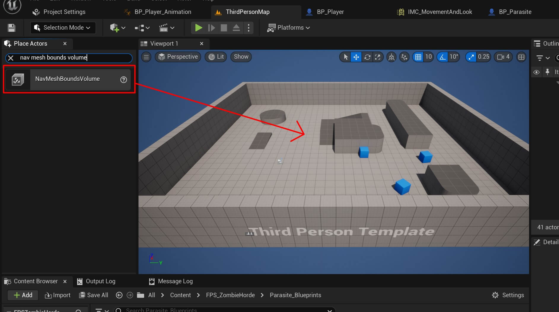
And to give it that information we need to drag the Nav Mesh Bounds Volume inside the map. To do that we need the Place Actors view which you can access from Window -> Place Actors:
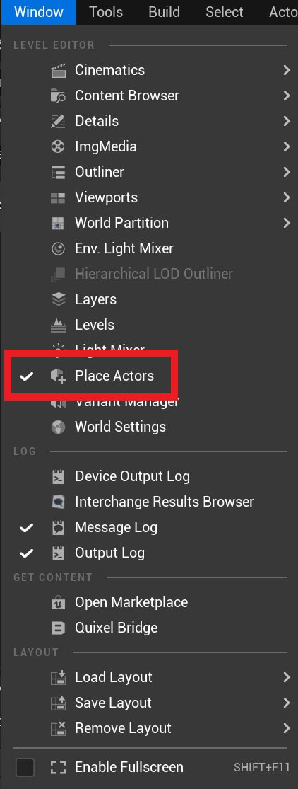
Inside the Place Actors window search for the nav mesh bounds volume and drag it in the map:
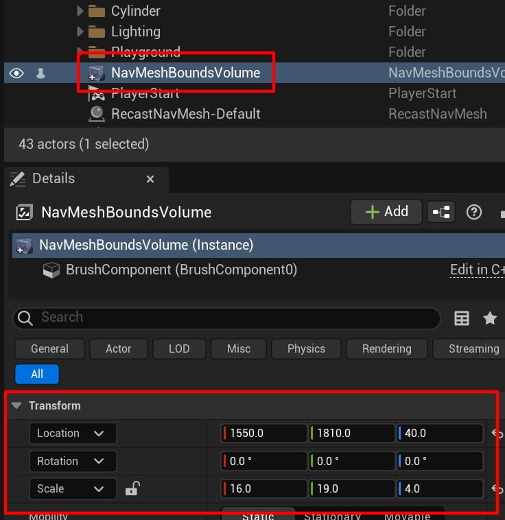
Select the Nav Mesh Bounds Volume in the Outliner tab and set the following values for the Transform component:
This will resize the Nav Mesh Bounds Volume to cover the whole level:
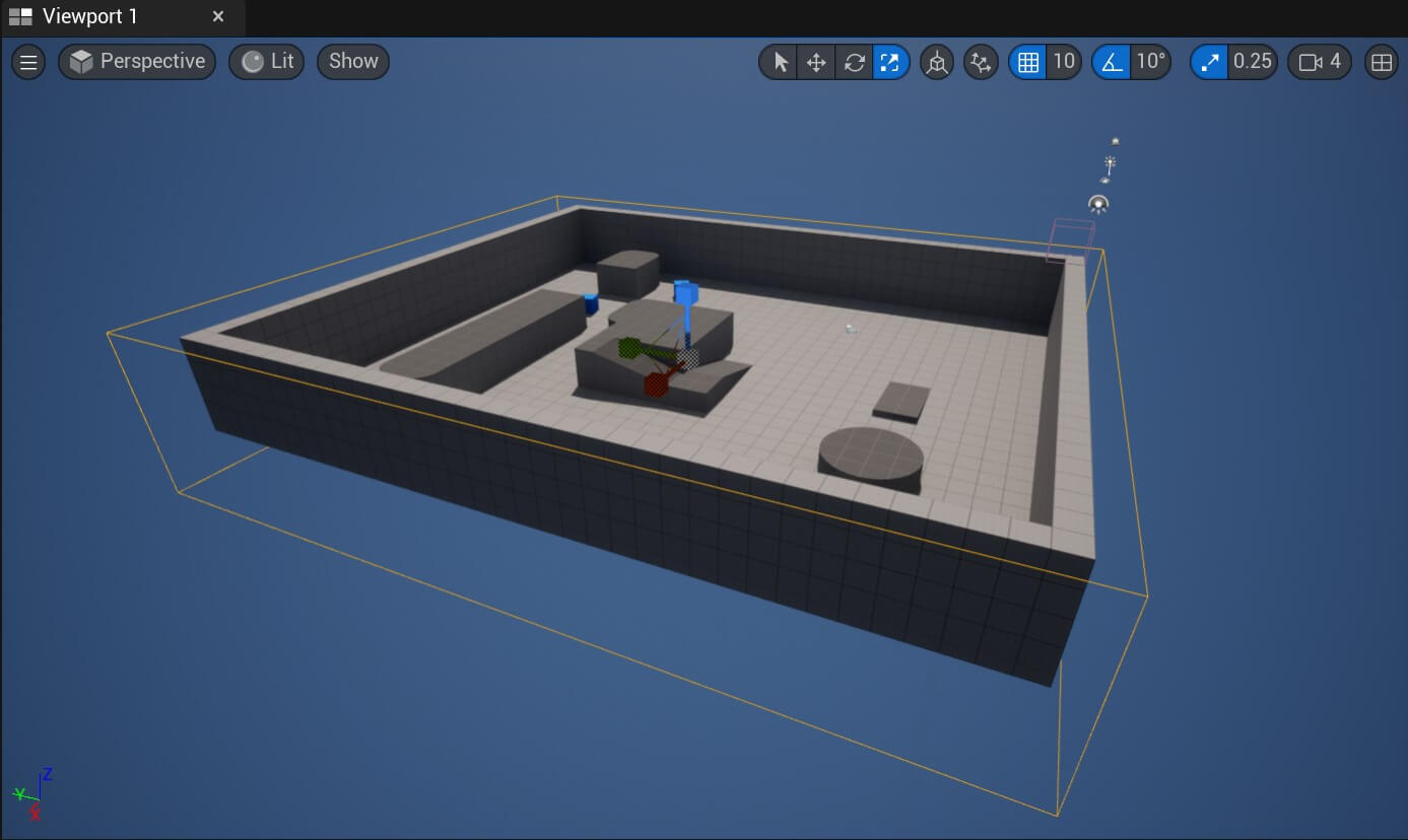
We need to do this because the Nav Mesh Bound Volume can only get the information of the environment which is contained within it. And when we resize it to fit the whole level then it will have the information about the whole level.
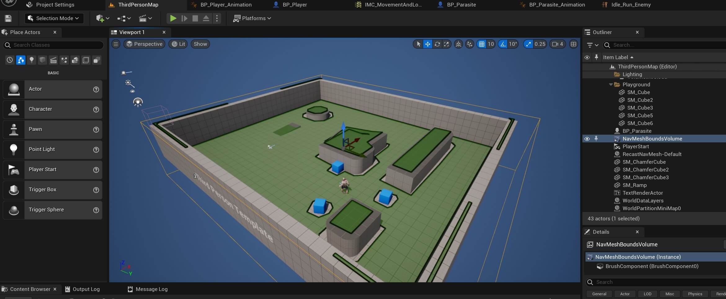
And we can check this by pressing the “P” button on the keyboard. When we do that everything that’s covered with the green color means that’s a navigationable are:
Now when we test the game we’ll see that the enemy is following the player:
Now the enemy follows the player and we also saw when it reached the player that it attacked him which was denoted with the Print String node which printed in the top left screen “Enemy attacked player.”
One thing was missing though and that is the enemy animation. The enemy was moving but it was not being animated.
Before we provide the solution for that we’re giving you an assignment to fix it.
But essentially what you have to do is inside the EventGraph for the BP_Parasite_Animation blueprint add the following nodes:

Now when we test the game we’ll see that the enemy is animating:
Dealing Damage To The Enemy
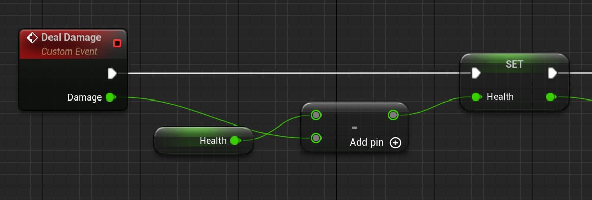
To deal damage to the parasite enemy we first need to create a custom event. So inside the BP_Parasite add the following nodes:

We created a custom node called Deal Damage which takes a float parameter. You can create a parameter for a custom event in the Details tab:
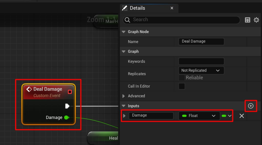
The parameter can be of any type but for our purpose here we need a float.
So we take the Damage parameter and we subtract it from the Health value then we set the new Health value.
After that we take the new Health value and we test if it’s less than or equal to 0 meaning we are testing if we should destroy the enemy because it’s health dropped to 0 or below 0:

If that is true we’ll execute the following nodes:
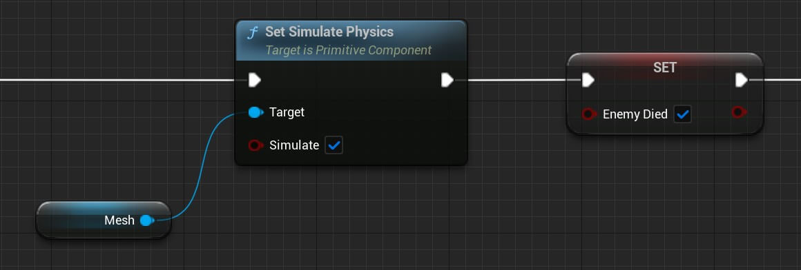
The Set Simulate Physics node will simulate a ragdoll like effect on the mesh and make the enemy fall down. We also set the Enemy Died to true because the enemy has no more health left to be alive in the game.
Next, we are going to increment the enemy kill count inside the BP_Player, but for that we first need to create a function called Increment Kill Count inside the BP_Player:
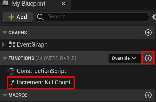
Inside the Increment Kill Count function we are going to increase the Kill Counter variable value by 1:

Now we can go back inside the BP_Parasite and finish the Deal Damage event node by adding the following nodes:

Basically we’re getting a reference to the BP_Player blueprint, calling his Increment Kill Count function we just created to increase the kill count by 1, then delaying 1 second and destroying the enemy actor.
You can copy the nodes for the Deal Damage event from here:
We are still not done because in order to deal damage to the enemy we need to go back in the BP_Player blueprint at the end of the shooting functionality when we spawn emitters at the location where the bullet hits and add the following nodes:
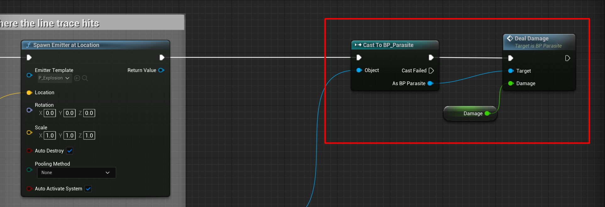
We are getting a reference to the BP_Parasite and calling its Deal Damage event to deal damage to the enemy, and the object we’re passing as a reference is the Hit Actor we get from the Break Hit Result:
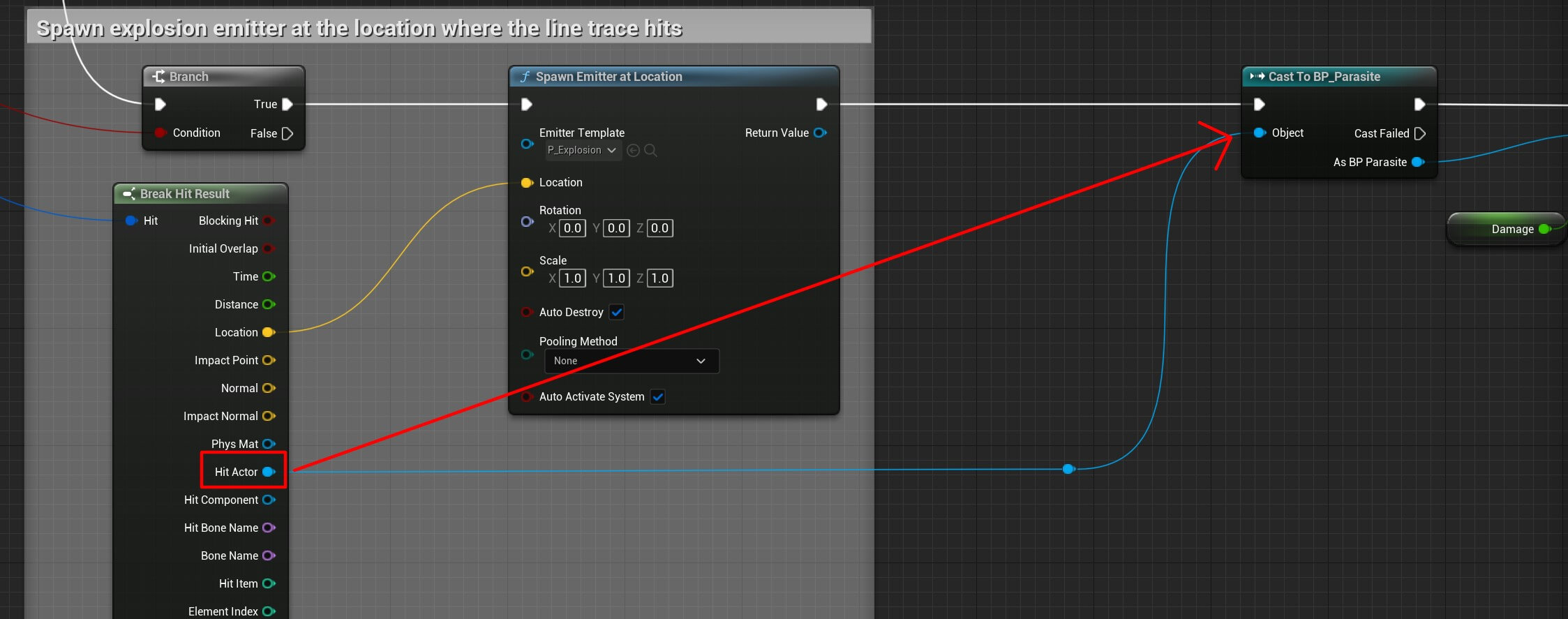
Now we can run the game and see the result:
Well…
This backfired…
And I can already hear you screaming “TEACHER THIS IS NOT WORKING WHAT SHOULD I DOOOOOO”
Calm down.
We need to do one more thing so that we can deal damage to the enemy. Inside the BP_Parasite, select the mesh component in the Details tab find the Collision settings:

In the collision settings for the Collision Presets select the Custom option and set the settings as you see below in the image:
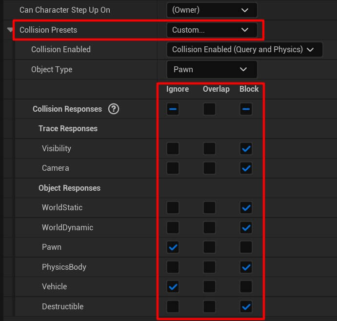
Also for the Collision Enabled option click on the drop-down list and select Collision Enabled (Query And Physics):

These settings are going to enable the line trace we’re drawing to collide with the parasite enemy.
So now when we run the game and test it we have this result:
Now when we hit the enemy we deal damage to it and when its health value drops to or below 0 the enemy dies. We also saw the ragdoll effect when the enemy fell down which is created with the Simulate Physics node.
Dealing Damage To The Player
To deal damage to the player we need to do the same thing we did for the enemy. Inside the BP_Player create a custom node called Deal Damage and add the following nodes:

This is the same thing we did for the BP_Parasite and the same explanations are valid here as well.
But opposite to the enemy actor, for our player we need to add the following nodes as well:

Essentially, when the player dies we need to disable the input because we don’t want to move the player when he dies in the game. Also, in case we are sprinting when the player dies we are calling the Unsprint Event to cancel the sprinting.
Lastly, we are delaying 2 seconds and then reloading the same level. Just make sure that the level name you put in the parameter is the same as the game level:
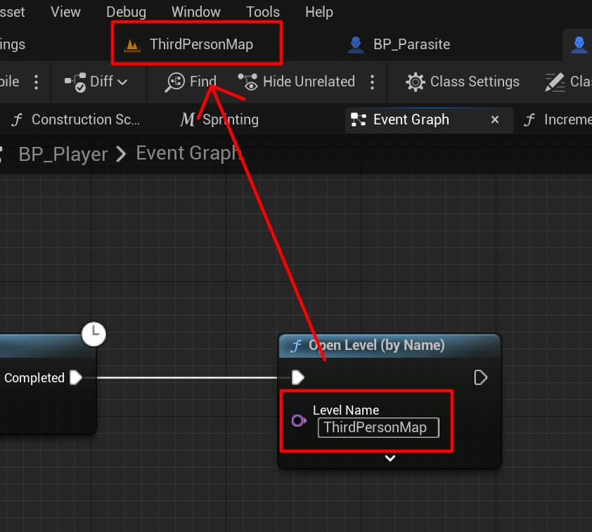
The last step is to go inside the BP_Parasite and at the end of the Chase Player node in the block which we commented with Deal Damage To Player, instead of calling the Print String node, we are going to call the Deal Damage node which we just created:
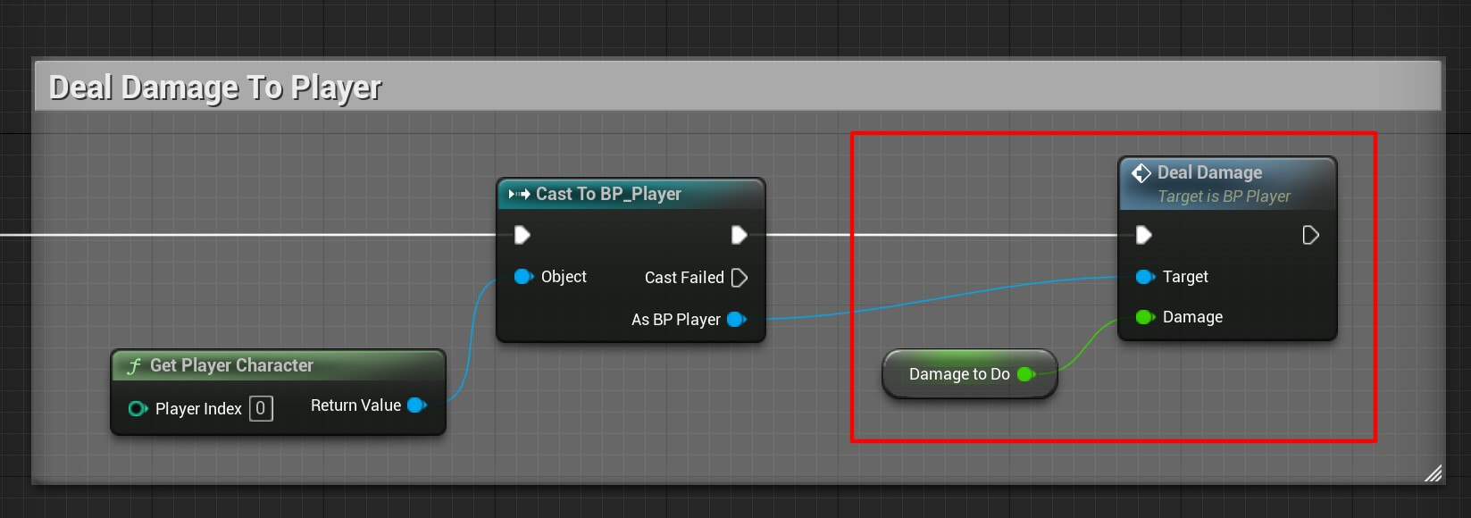
Now we can run the game and test it out:
After a few moments or attacks when the enemy gets close to the player the player character dies and then we restart the level and play the game again.
The reason why it takes time for the player to die is because of the attack delay we set on the enemy. We set the attack delay to a higher number because when you have multiple enemies in the game they will attack the player all at once and deal damage and thus killing the player faster.
Creating The UI HUD For Our Game
We are finished with the mechanics of our game. The last step is to display the game stats e.g. player’s health and kill count to the user who plays the game.
We’re going to start by created the UI hud, so inside the HUD folder create a new blueprint widget:
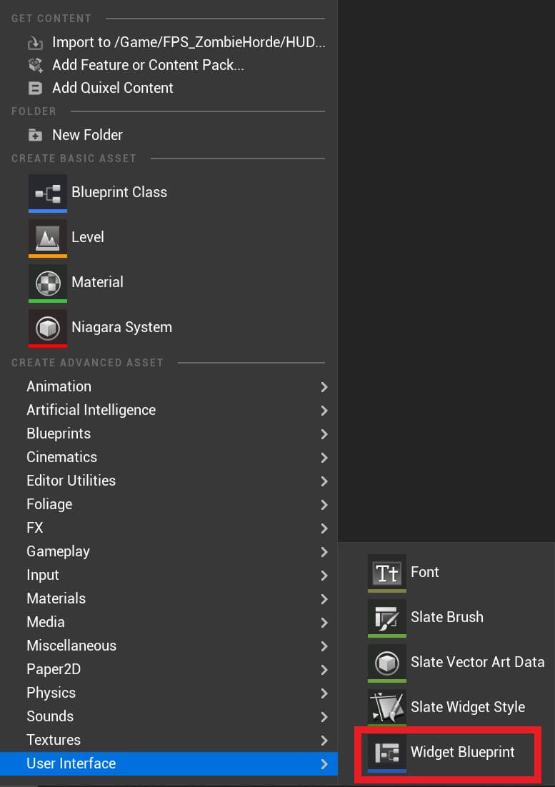
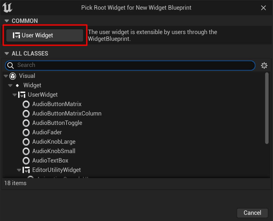
In the popup window click on the User Widget:
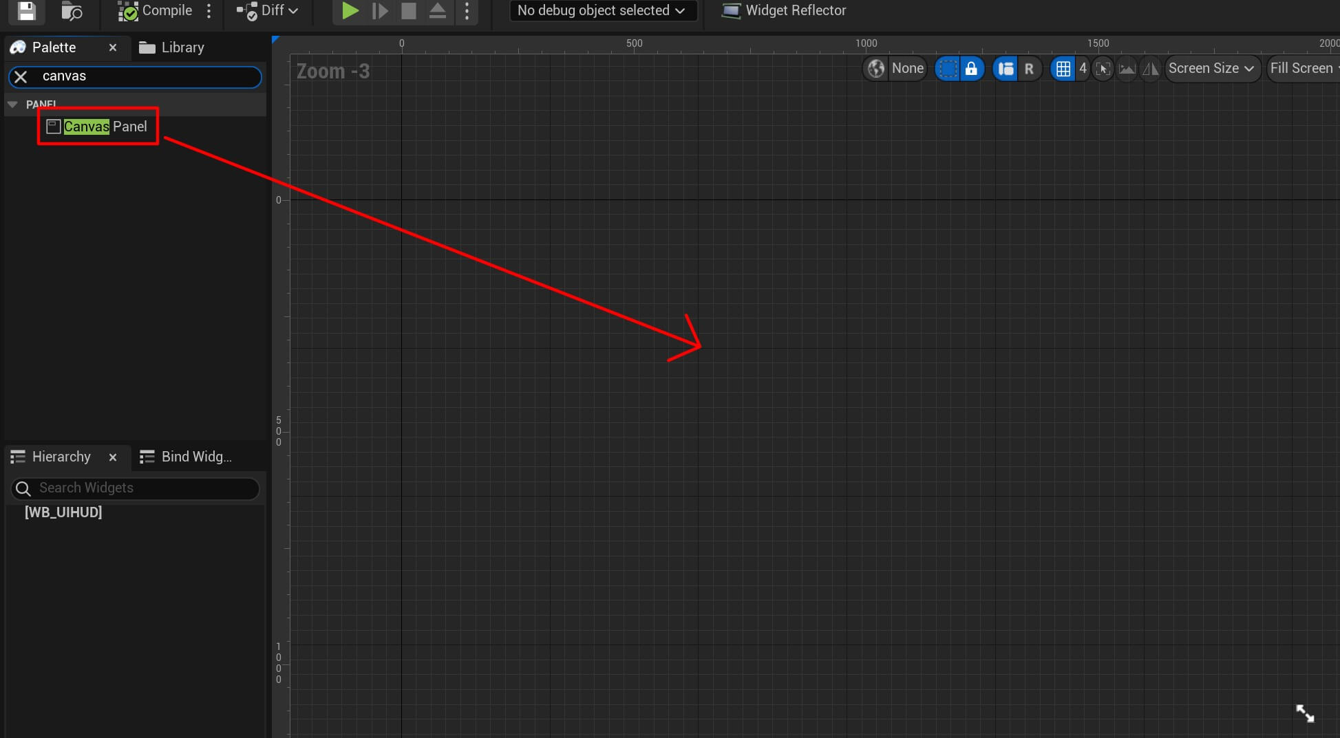
Name the widget WB_UIHUD and open it in the editor. The first we need to do is from the Palette tab on the left side search for the Canvas and drag it in the editor:
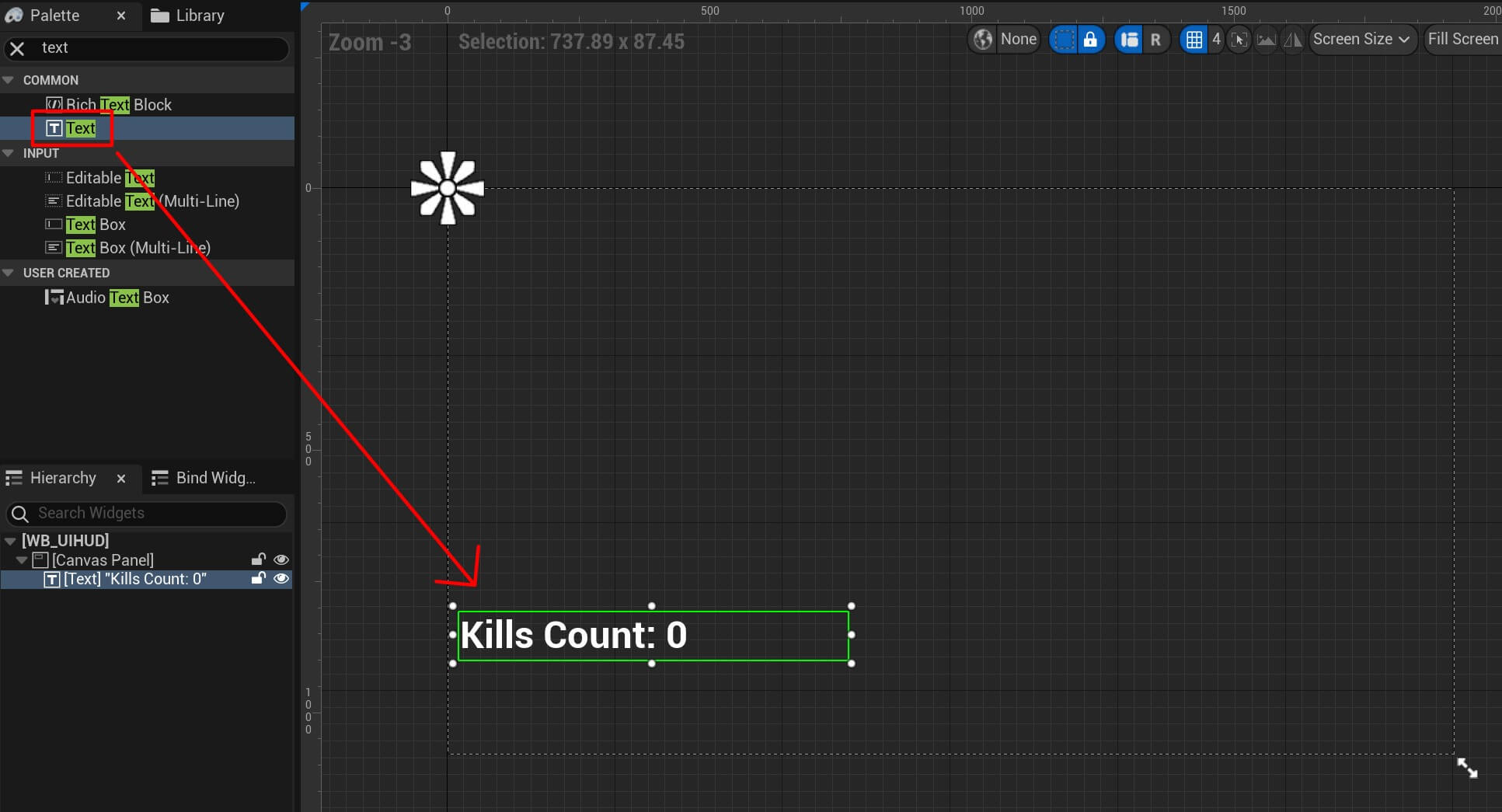
Next, we are going to search for a text widget and drag it in the canvas:
Move the anchor of the text widget at the bottom left corner by dragging it from the top left corner:
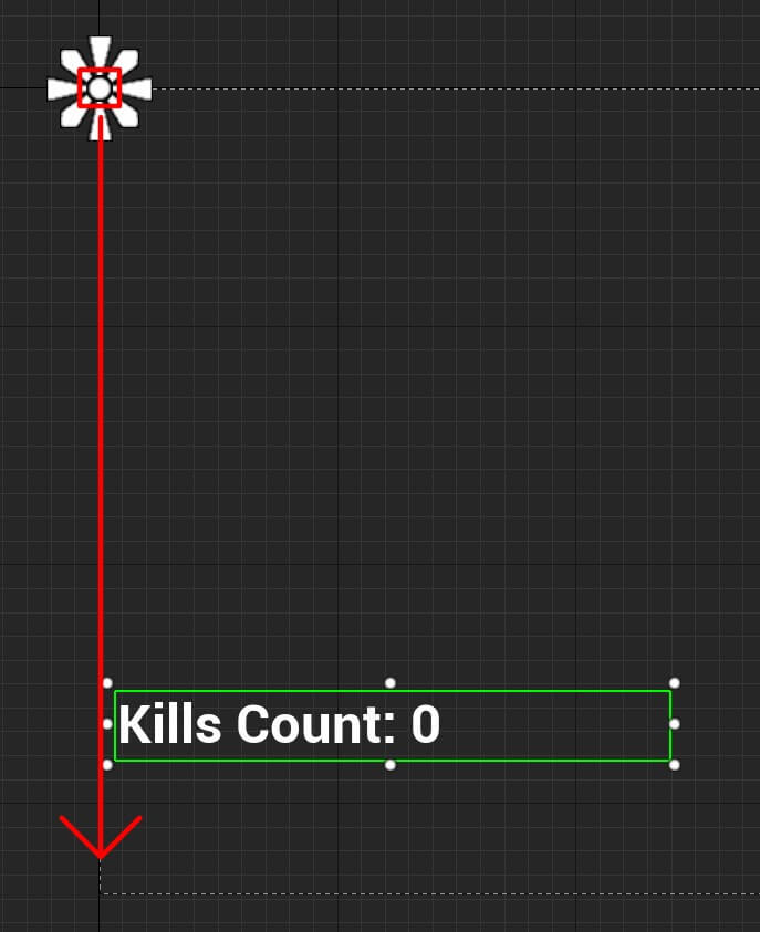
The anchor represents the starting origin of the UI widget. So when we set the anchor at the bottom left corner and set the position of the widget to be X = 0, Y = 0 it will position at the bottom left corner.
Same thing will happen if we move the anchor at the top right corner for example, and we set it’s position to X = 0, Y = 0, the widget will be positioned at the top right corner.
Next, change the settings for the text in the Details tab on the right side:
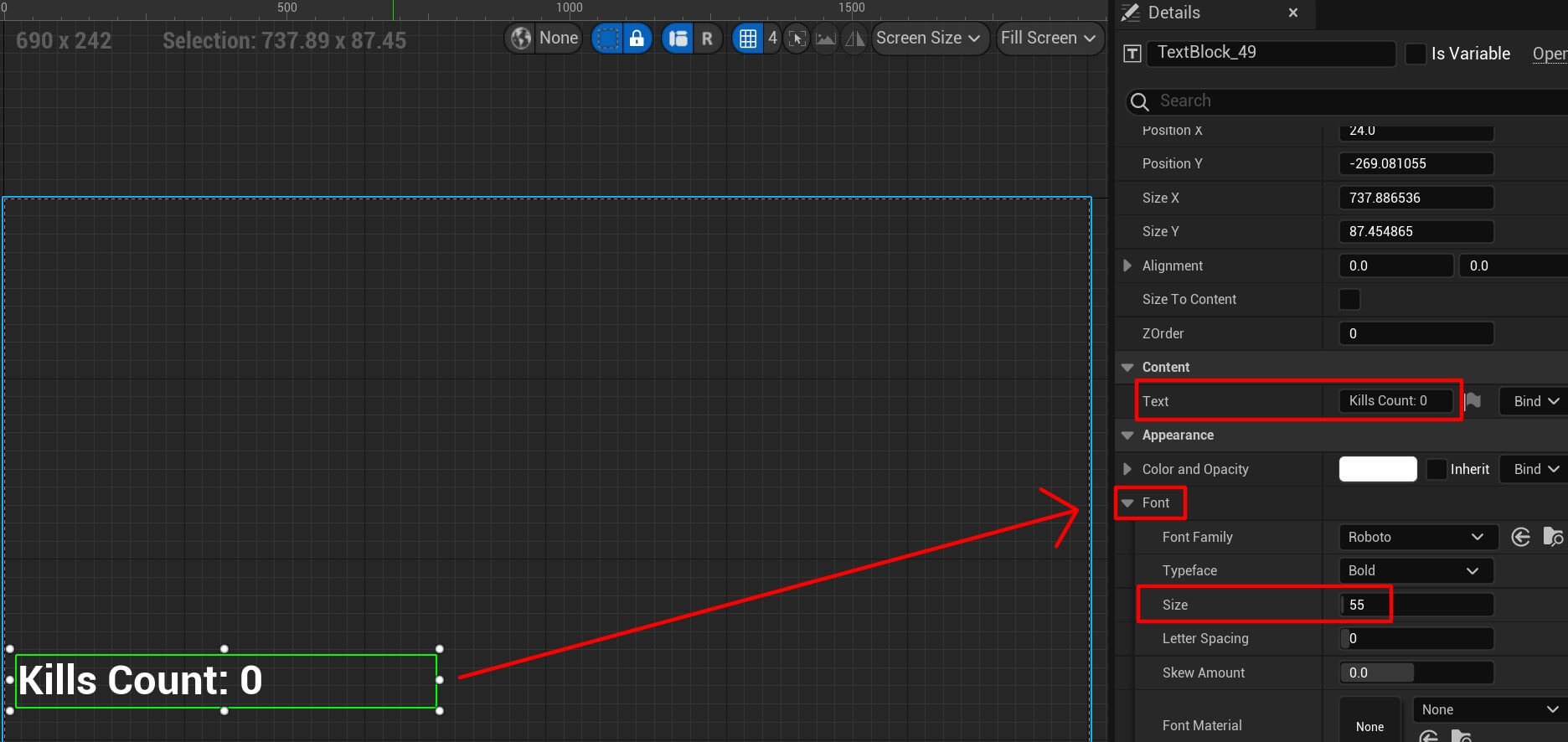
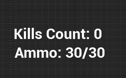
We changed the font size and we change the initial text that’s displayed. Next, duplicate the text widget with CTRL + C and CTRL + V or Right Click -> Copy and the Right Click -> Paste and move the duplicate texst widget below the original.
All options are going to stay the same except for the initial text which we are going to change to display the ammo:
We are also going to display the player’s health with the UI widget and for that we are going to use a progress bar which you can search in the Palette tab and drag it at the bottom left corner:
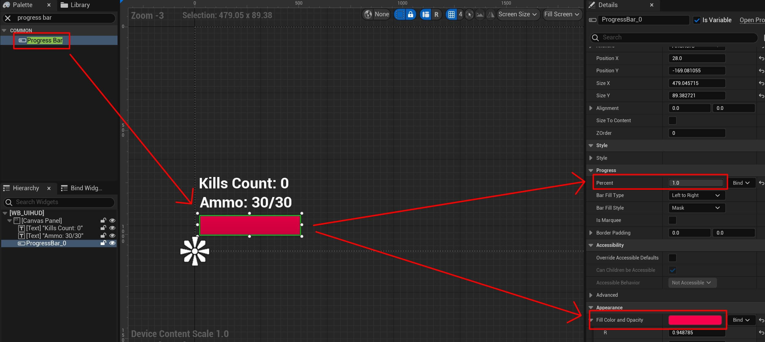
We’ve also moved the anchor of the progress bar at the bottom left corner, we changed the percent value to 1 which basically means it will fill the progress bar, and we changed the color.
To display this widget in the game we need to go inside the BP_Player blueprint and add the following nodes:

In the BeginPlay node after we call the Add Mapping Context we call the Create Widget node and specify in the drop-down list the WB_UIHUD widget we created, and lastly we are calling Add To Viewport node which will add the widget to the view port.
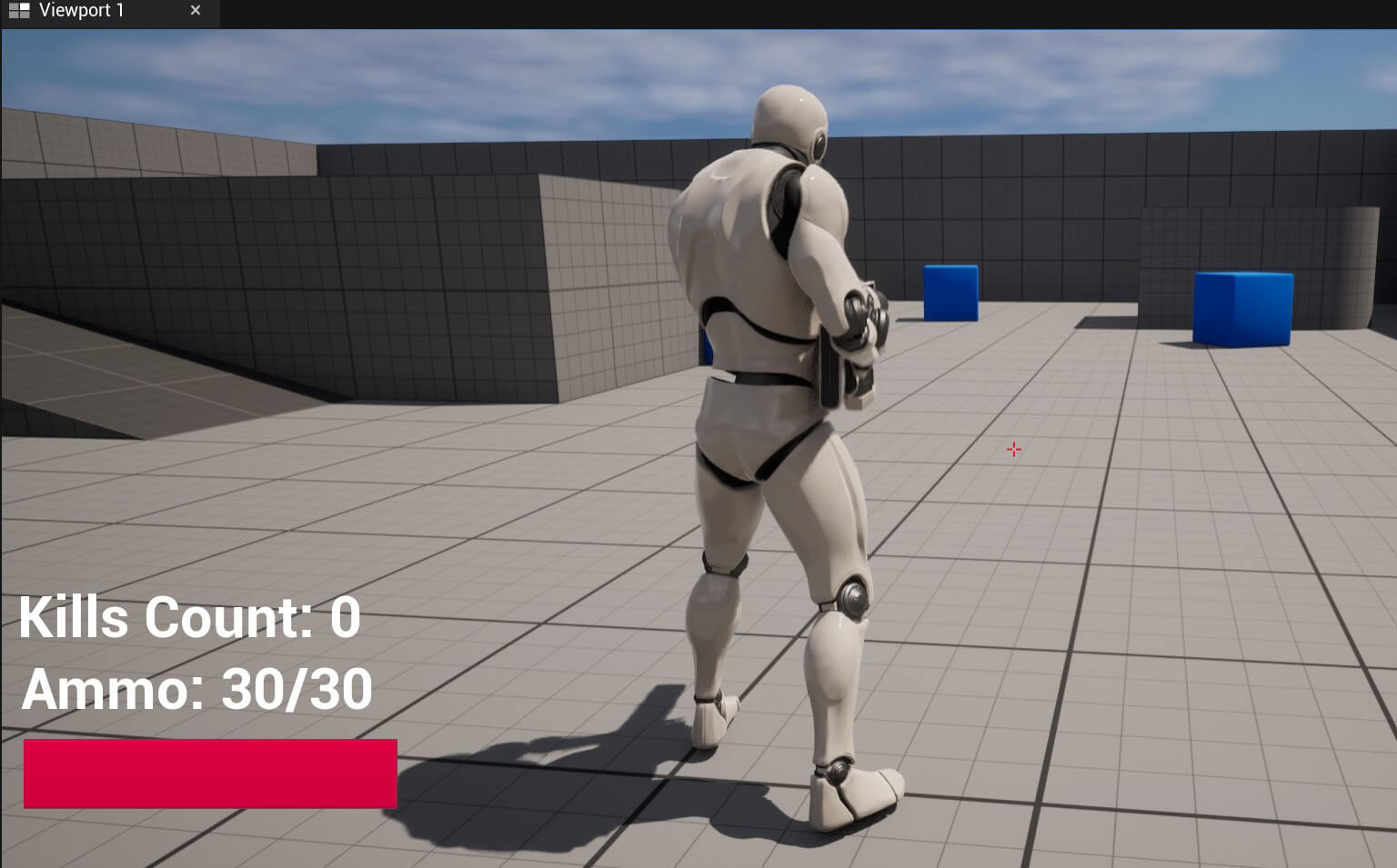
When we run the game we’ll see the UI hud:
Displaying Game Stats In The UI HUD
While the UI is showing in the game it still doesn’t have any functionality. To fix this, we need to go inside the Graph editor of the WB_UIHUD which you can access at the top right corner:
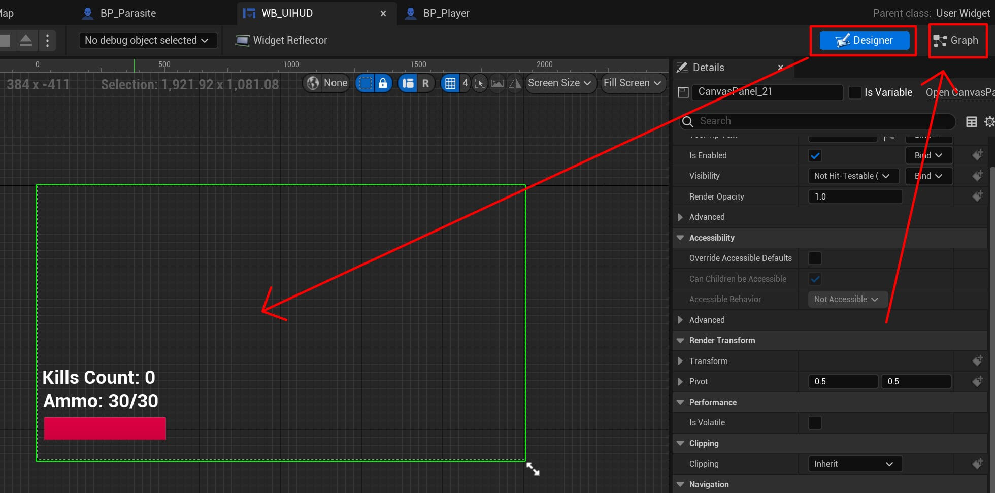
You’ll notice that we Designer tab which represents the visual part of the widget which is the one we just worked on, and next to him we have the Graph tab.
Click on the Graph tab and from the Event Construct we are going to get a reference to the BP_Player actor:
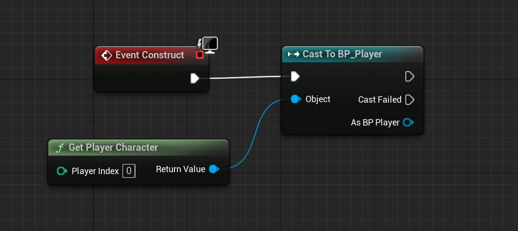
To get a reference to the BP_Player we can either create a variable like we did in prior examples above, or we can drag the line from the As BP Player returning value and then select promote to variable:
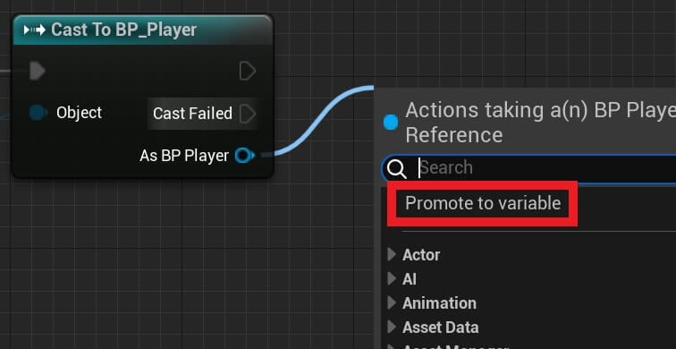
This will automatically create a BP_Player reference variable and assign it:

We’ve renamed the variable to Player just in case if you’re confused because you’ll probably see the name of the variabel As BP Player.
Now that we have a reference to the player actor we can go back in the Designer tab, select the kills counter text and from the Bind drop-down list create a new binding:

This binding is actually a function that is bound to that text widget and we can use that function to manipulate that text widget.
You can find the function inside the Graph editor in the Functions tab and you can also rename it which we already did:
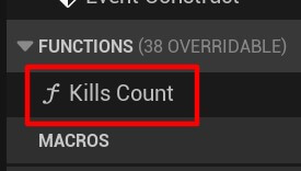
Next, create a new variable type of string:

Give that variable a default value of “Kills Count: “:

Notice how we have space at the end of the string because we want to appent an integer which is the kills count value.
And to do that, we’ll add the following nodes:

The Build String node will build a new string from the parameters we pass to it. The Append To parameter is the first string to which the integer will be appended.
We are using the Kills Count Txt variable which we created above and then we are appending the Kill Counter which we got from the Player reference.
And finally we are plugging that value in the Return Value for the Return Node.
So now when we test the game the kills counter will count how many zombies we killed:
We’ve added an extra zombie just so that we can see the kill count go to 2 when we kill them both.
Now we are going to repeat the process for the ammo text. But before we show you how to do it, you have an assignment to do it on your own.
It’s the same thing we just did for the kills count but we also need to add one more string after we append the ammo count.
We’ll start with creating a binding for the ammo text, we’ll name it Ammo Counter and add the following nodes:
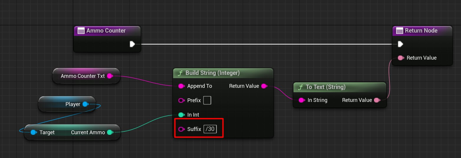
We created a local variable of string type and added “Ammo: ” value in it.
Next, from the player reference we get the Current Ammo value and we also add the suffix “/30” at the end so that it will display the ammo like X/X.
This is how it looks like when we run the game:
Whenever we shoot with the gun the ammo count goes down and when we reload the gun the ammo goes back to its initial value.
The last step with the UI Hud is to display the health of the player. So inside the Designer tab, select the progress bar and create the binding for the percent:
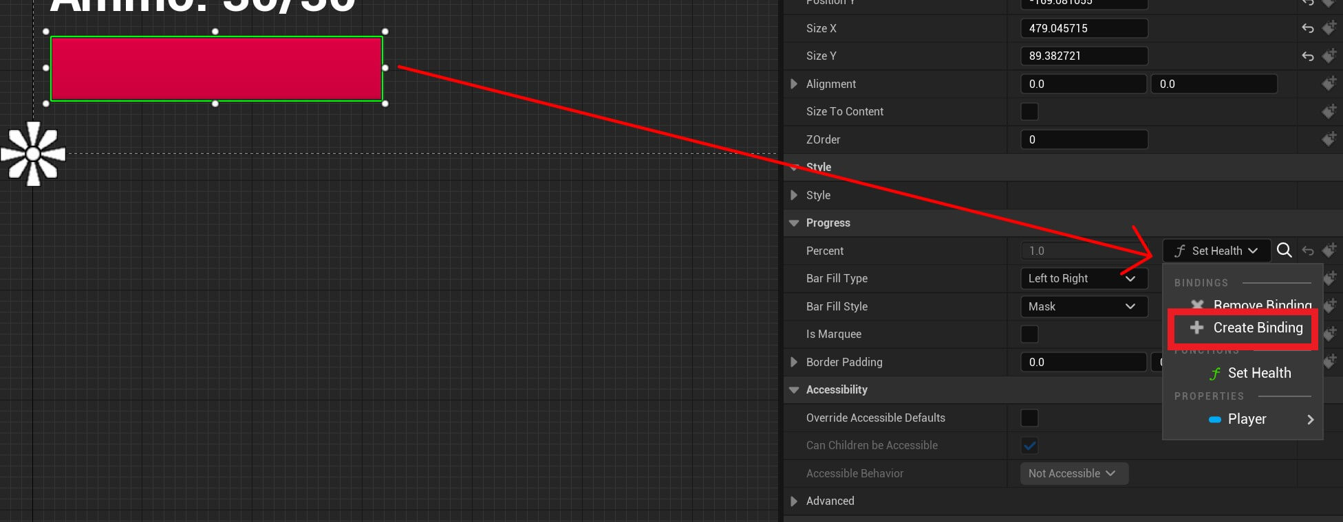
Name that binding Set Health and add the following nodes:
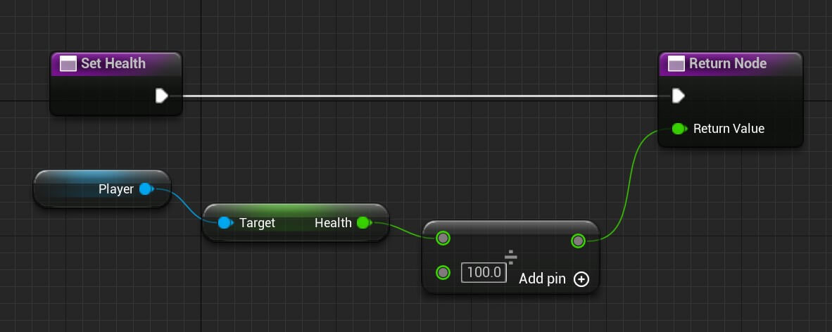
We are getting the health value from the player, then we are diving that value by 100 because the percent value for the Progress Bar widget goes from 0.0 to 1.0.
So if the player’s health is 90 and we divide that by 100 we get 0.9 and that’s the value which will be set in the progress bar.
This is how it looks like when we test the game:
Zombie Spawner
The last step is to creat a spawner who is going to spawn new enemies in the game over a time interval.
Since this is the last thing we’ll do for our game we’re not going to create a separate folder just for the zombie spawner blueprint, but if this was a bigger game definitely group all your assets for better management.
So inside the FPS_ZombieHorde we are going to Right Click -> Blueprint Class and from the next window select the Actor class as the parent class:
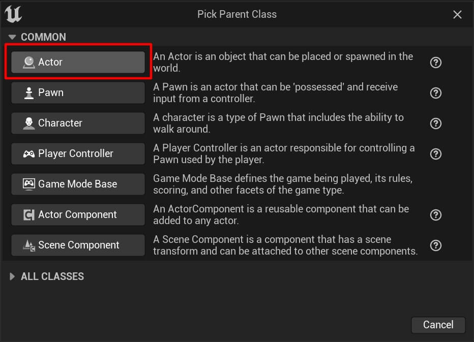
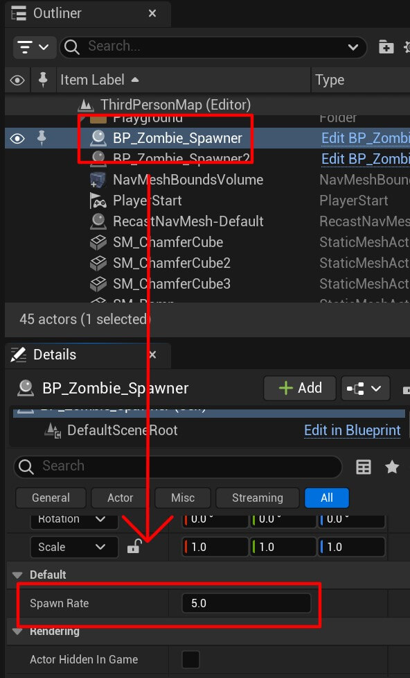
Name the new blueprint BP_Zombie_Spawner and open it in the editor. Inside the BP_Zombie_Spawn first we’re going to create a new float variable, call it Spawn Rate, make it visible in the blueprint instance by clicking the eye icon and set the initial value to 5:

Then add the following nodes:
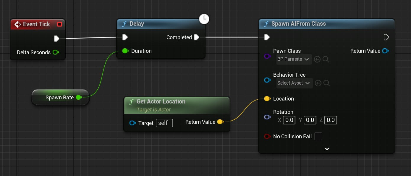
First we are calling the Delay node and we’re passing the Spawn Rate which will delay the node using its value.
And becase we clicked the eye icon for the Spawn Rate, we can edit its value for every blueprint instance we create.
Lastly, we’re calling the Spawn AIFrom Class node which will spawn the AI class we provide in the Pawn Class paramter. And the class we provided is BP_Parasite from the drop down list.
Now, instead of adding the zombies in the game directly, we add the spawners which will spawn the zombies:
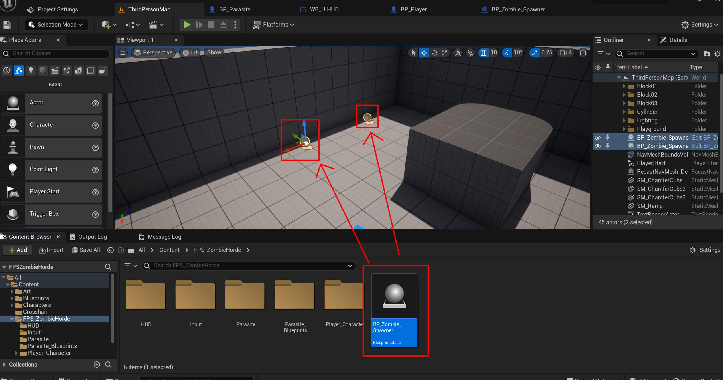
To randomize the spawning, select one of the spawners in the Outliner tab and in the Details tab change the Spawn Rate value to any number you wish:
And when we perform the final test of our game, this is how it looks like:
Final Assignment
While the game is working and we can play it, there are 2 bugs in the game.
The first bug is when the enemy dies and we continue shooting it, it will still count it as a kill count and the kill count score will increase.
And the second bug is when the enemy dies near the player and touches him, he still deals damage to the player.
This is how that looks like in the game:
As you saw in the video, when the first zombie was killed we contined to shoot him and the kill count was increasing.
Also, when the enemies were close to played and they died, they dealth damage.
We leave these two bugs for you to fix, and we encourage you to try and do that because that’s the best way to learn.
And after you fix these two bugs, because the title of this tutorials FPS Zombie Horde – your last assignment will be to change the camera angle of the player to make this game a first person shooter instead of the third person shooter which it currently is.
We’ll not provide a solution for that here, but for those of you who are interested in the solution, you can send us an email at support@awesometuts.com and we’ll provide the solution.
Where To Go From Here
For more Unreal Engine blog tutorials you can explore our blog by clicking here.
You can also check out our flagship program called Game Dev Pro which has already helped thousands of people become pro game developers and get hired in the best game studios in the world.

Comments are closed.