In part 1 of this tutorial series we created our game level and we learned about working with Actors inside the Level Editor.
In this part of the tutorial we are going to learn what are game modes, and we are going to create our Player Actor and make him move.
Where Is The Player In The Game
As you can see, we have a first person view for the game and we can fly in the level.
We can pass through the level elements such as the Obstacle Walls, but we can fly above them to avoid them.
While we can control the movement, we don’t see the Player Actor that we are controlling. We can do that by using the Eject button:
The Player Actor that we are currently controlling is actually a Sphere object.
After we press the Eject button and we click on that Sphere object inside the Level Editor you will notice inside the World Outliner the name of that Sphere is DefaultPawn.
This is the default Player Actor that we can control when we create a new level and because of his limited functionality we can only use him to move around and check out the level.
Player Start Point
First, how do we set up a starting point where the Player Actor is going to spawn when the game starts.
The start point is determined with the Player Start Actor that comes by default with every level we create:
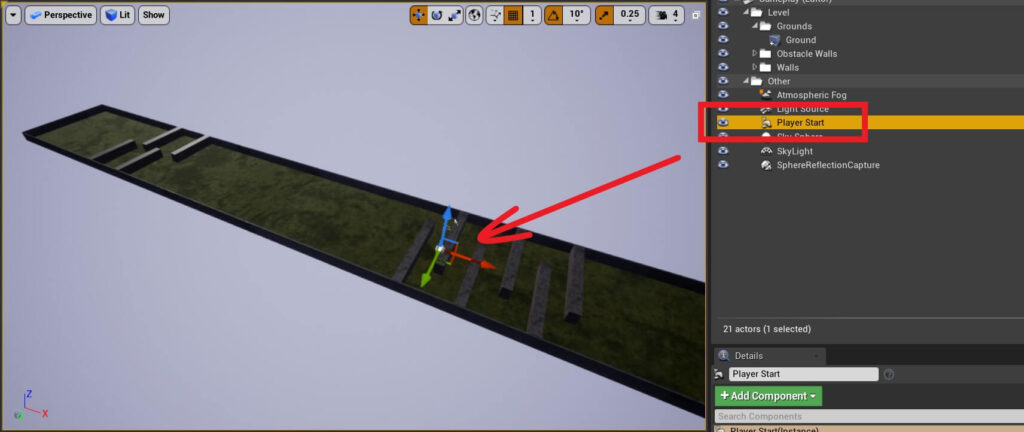
Which means, we can take the Player Start Actor and position it wherever we want in the level, and when the game runs this is where our Player Actor is going to be spawned.
Since we want the Player Actor to start at the beginning of the level right in front of the Start Wall Actor, we are going to set the Location values of the Player Start Actor to the following:
- X = -9720
- Y = 0
- Z = 112
The Default Game Mode

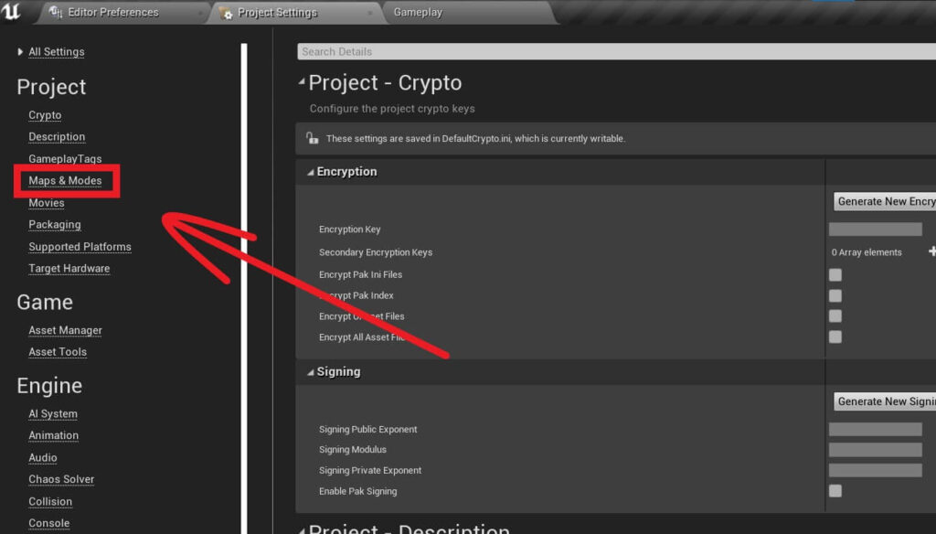
Inside the Maps & Modes tab under Default Modes click on the drop down list on the left of the Selected Game Mode:


The Default Pawn Class is set to DefaultPawn, which is the Player Actor that we saw in the game when we used the Eject button.
A Pawn object is a physical representation of a Player within the game world.
Basically a Pawn is an object that is placed in the level, same as the Actor, so if you refer to the game character as a Pawn or an Actor it’s one and the same thing.
The difference between them is that the an Actor is something you place in the game world, it can be a game character, a cube, a sphere and so on.
A Pawn is a type of Actor that can be possessed and receive input and we can control it.
But again, in my posts whenever I say Pawn or Actor that is referring to the same thing – a game object inside the level.
We also see other default classes like HUD Class, Player Controller Class and so on.
At the moment these are not important, we will talk about them when we want to use them with a practical example. For now, we are going to focus on the Default Pawn Class.
The Default Pawn Class is selected with the Default GameMode which currently is GameModeBase:

Creating A Custom GameMode
Inside the Content root folder in the Content Browser tab Right Click -> New Folder and give it a name Blueprints.
Inside the Blueprints folder Right Click -> Blueprint Class:


We are going to inherit from GameMode so select it, and then press the Select button at the bottom of the window.
This will create a new Blueprint in the folder where you right clicked to create a new Blueprint, in our case the Blueprint folder.
For the global GameMode I usually give the name for the Blueprint using the name of the project, so you can give that Blueprint the following name: BP_ParasitePlatformer_GameMode.
I said global GameMode above, becase we can also create GameModes for every level that we have, and we will see examples of that.
I always add BP in the beginning of the Blueprint name so that I know that is a Blueprint.
This is very useful when we have a lot of files in our project and we are looking for specific things to use.
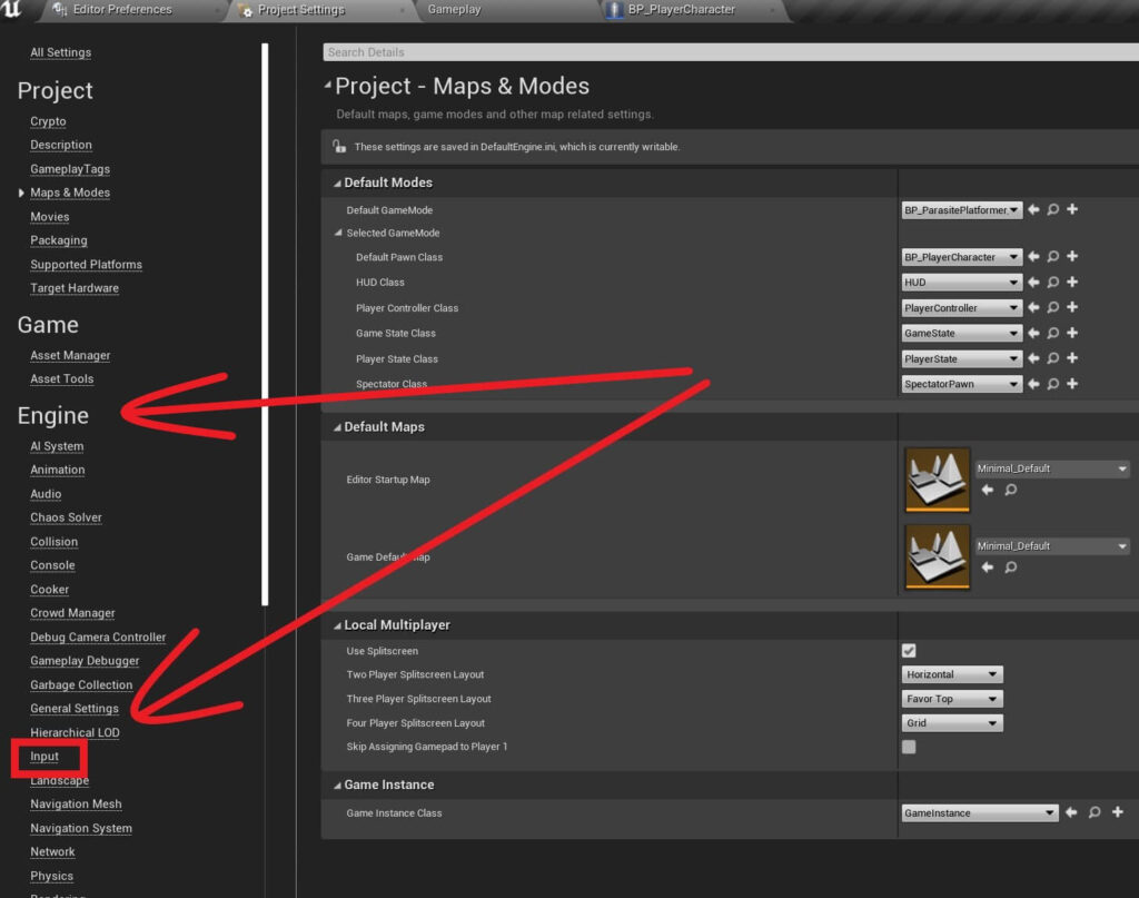
Now that we have a custom GameMode, we can go back in the Project Settings -> Maps & Modes and from there, click on the drop down list for the Default GameMode and select the custom one we just created:

Now that we select a custom GameMode, we can see that the fields below are now editable:
Creating The Player Actor
While we can select a custom Default Pawn now,we didn’t create one.
To create a custom Pawn, inside the Blueprints folder Right Click -> Blueprint Class.
This time we are going to inherit from the Character:

When we press the Eject button after we run the game we don’t see the Sphere object that we saw in our previous testings.
That is because now our BP_PlayerCharacter is spawned in the game and we saw that inside the World Outliner tab where we selected our custom PlayerCharacter.
We could not see him inside the game however. And the reason for that is we didn’t attach any mesh components on our custom PlayerCharacter and we didn’t add any code to it that’s why we could not even move when we run the game.
The Blueprint Editor Window
To edit the BP_PlayerCharacter Blueprint, double click it to open it. If this is your first time opening a Blueprint the Blueprint Editor window will be floating so you will have to dock it, and you can do that wherever you wish:
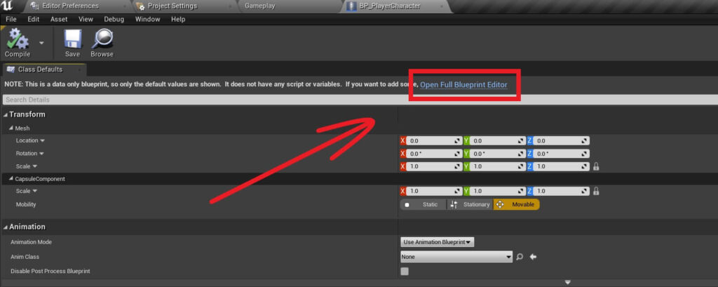
It can also happen that you don’t see the editor window inside the Blueprint Editor, for that you can simply click on the Open Full Blueprint Editor button:
This is how the Blueprint Editor window looks like:
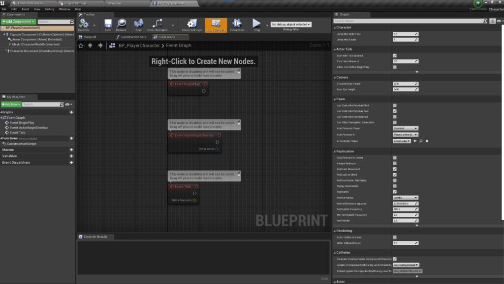
At the top left corner we have the Components tab where we can see the components that are attached on our Blueprint, and from there we can attach new components on our blueprint:


On the right side you see the Details tab which will display information about selected components and functions:

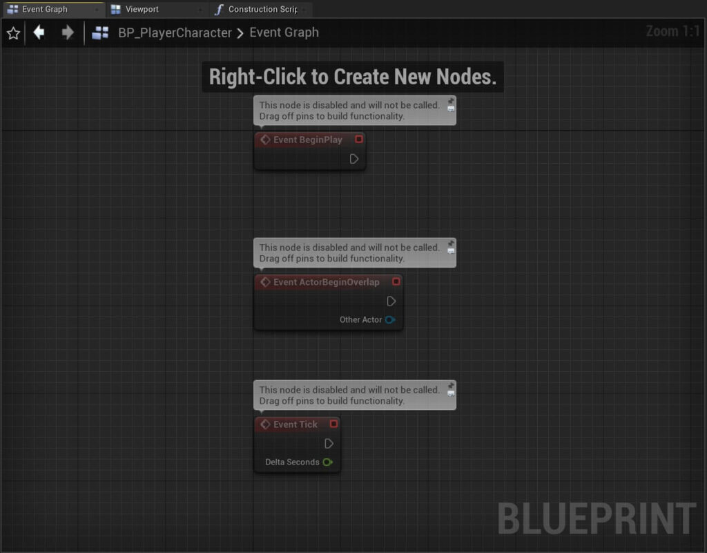
Inside the Event Graph is where we will place our Blueprint code e.g. the nodes that make the code.
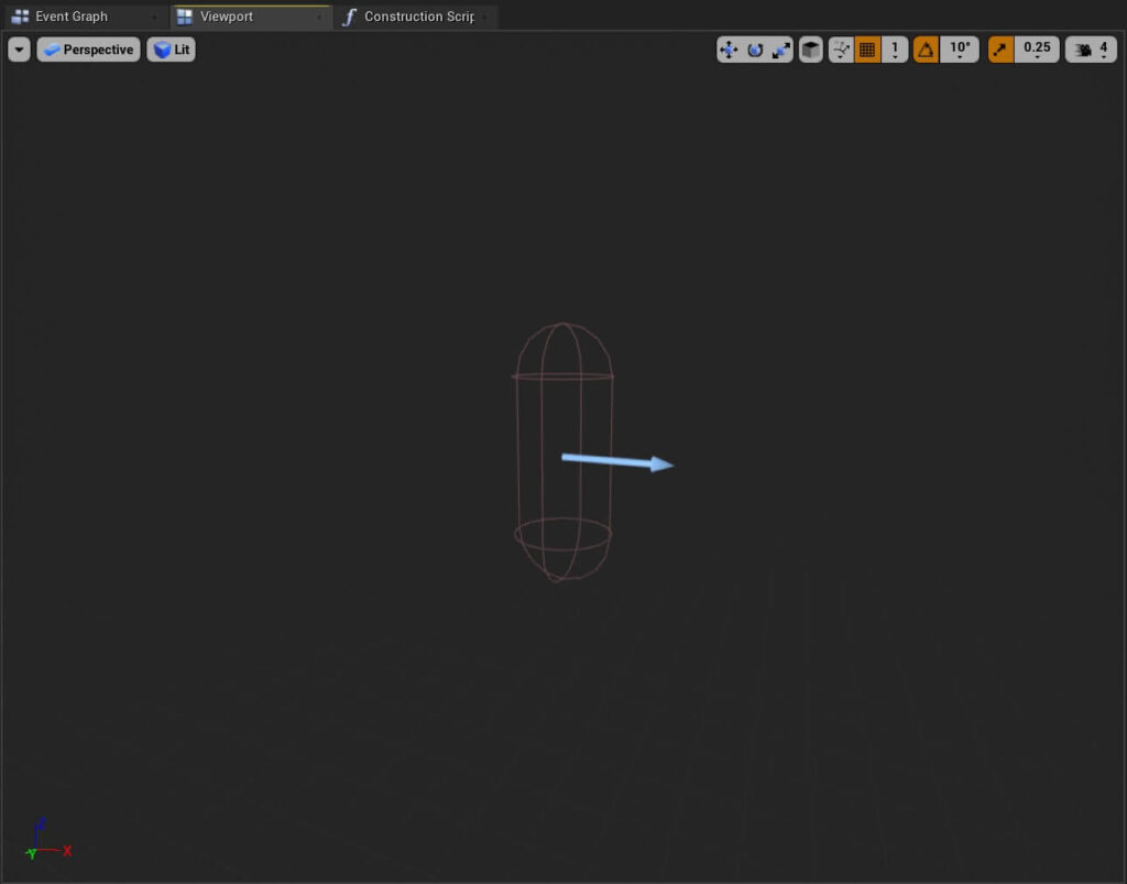
Next we have the Viewport tab:
Making The PlayerCharacter Visible In The Game

Every time you make a change you want to apply to your current Blueprint, first click the Compile button and then the Save button in the Toolbar:
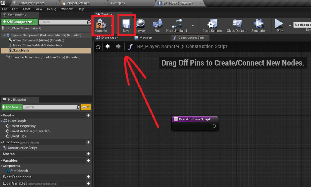

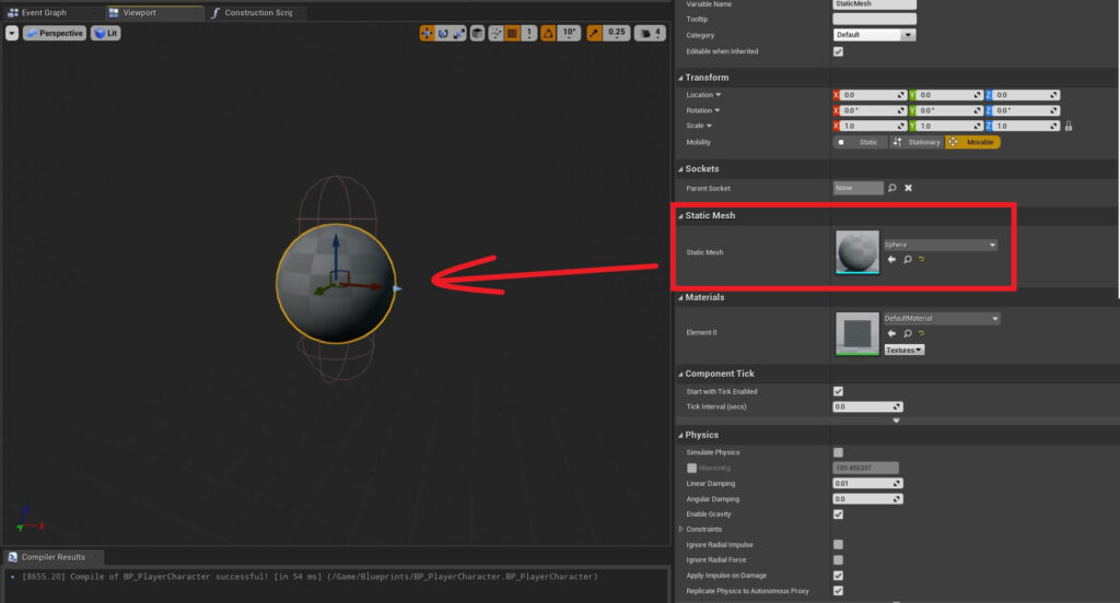
After you deleted the Static Mesh component press the Compile and then Save buttons to apply those changes to the Blueprint.
Adding The Camera Component To The PlayerCharacter
Inside the Blueprint Editor for the PlayerCharacter in the Components tab click on the Add Component button and filter for the Camera component and attach it.
We already did this in the previous step when we attached the Static Mesh, the process is exactly the same except that instead of attaching a Static Mesh, we will attach a Camera component:


You can play with the Location of the Camera component and you will see every time you change the values the Camera component will be positioned relative to the position of the PlayerCharacter Blueprint.
Setting Up The Movement Input
We only have the Camera component attached on the PlayerCharacter Blueprint, so if we run the game now everything will be the same.
We have our first person view, we are standing in one place and we can’t move. To fix this, we need to set up the input first.
The input set up is located in the Project Settings which is under Edit -> Project Settings.
Inside the Project Settings click on Input which is located under the Engine category on the left side:

You will notice that some Axis Mappings have multiple keys that we can press to trigger them.
As you can see from the example above, you can add and remove extra inputs for every Mapping.
The same way you can also remove the Mapping by pressing the X button on the right side of the Mapping.
Unreal Engine Coordinate System

What does that mean?

As in any 3D space we have the X, Y, and Z coordinates.
From the image you can see that the X coordinate is the left – right, Y is the Up – Down, and Z is the Forward – Backward coordinate.
Another thing that you will notice on every coordinate is that we have a positive and a negative side.
On the X axis left side is the negative side and right side is the positive side. On Y axis up is positive, down is negative and on the Z axis forward is positive and backward is negative.
This is really important to know because if we want to move an Actor in a certain direction we need to know if that direction is positive or negative.
This is where the Scale value comes in. We use the Scale value and multiply the movement with it depending on the direction where the Actor is moving.
This is why for some directions the Scale value is 1 and for others the Scale value is -1.
To be more specific, for A and Left the Scale value is -1 because when we press one of the two keys we will move to the left side.
For D and Right the Scale value is 1 because when we press one of the two keys we will go to the right side.
The same explanation goes for the keys under the MoveForward Axis Mapping, the Scale value for W and Up is 1 because when we press one of the two keys we will move forward.
And the Scale has a -1 value for S and Down because when we press one of the two we will move backwards:
Where To Go From Here
In this tutorial you learned what is a Game Mode, how to create Blueprints, and how to set up the Input system.
In the next part of this tutorial series titled Moving The PlayerCharacter With Visual Code you will learn how write code inside the Blueprint editor and how to move Actors in the game.
Comments are closed.